Passive Components Blog
No Result
View All Result
  • Home
  • NewsFilter
    • All
    • Aerospace & Defence
    • Antenna
    • Applications
    • Automotive
    • Capacitors
    • Circuit Protection Devices
    • electro-mechanical news
    • Filters
    • Fuses
    • Inductors
    • Industrial
    • Integrated Passives
    • inter-connect news
    • Market & Supply Chain
    • Market Insights
    • Medical
    • Modelling and Simulation
    • New Materials & Supply
    • New Technologies
    • Non-linear Passives
    • Oscillators
    • Passive Sensors News
    • Resistors
    • RF & Microwave
    • Telecommunication
    • Weekly Digest

    Transformer Safety IEC 61558 Standard

    ESR of Capacitors, Measurements and Applications

    Murata Christophe Pottier Appointed President of EPCIA

    3-Phase EMI Filter Design, Simulation, Calculation and Test

    YAGEO Unveils Compact 2.4 GHz SMD Antenna

    KYOCERA AVX Releases Antenna for Iridium Satellite IoT Applications

    Molex Releases Industry-First Quad-Row Board-to-Board Connectors with EMI Shields

    Image credit: Samtec

    How to Match the Right Connector with Protocol Requirements

    Smoltek CNF-MIM Capacitors Pass 1,000h Reliability Test

    Trending Tags

    • Ripple Current
    • RF
    • Leakage Current
    • Tantalum vs Ceramic
    • Snubber
    • Low ESR
    • Feedthrough
    • Derating
    • Dielectric Constant
    • New Products
    • Market Reports
  • VideoFilter
    • All
    • Antenna videos
    • Capacitor videos
    • Circuit Protection Video
    • Filter videos
    • Fuse videos
    • Inductor videos
    • Inter-Connect Video
    • Non-linear passives videos
    • Oscillator videos
    • Passive sensors videos
    • Resistor videos

    Transformer Safety IEC 61558 Standard

    3-Phase EMI Filter Design, Simulation, Calculation and Test

    Transformer Design Optimization for Power Electronics Applications

    Common Mode Chokes Selection for RF Circuits in Next-Generation Communication Systems

    Capacitor Self-balancing in a Flying-Capacitor Buck Converter

    How to Select Ferrite Bead for Filtering in Buck Boost Converter

    Power Inductors Future: Minimal Losses and Compact Designs

    Percolation Phenomenon: Degradation of Molded Power Inductors in DC/DC Converters

    Connector PCB Design Challenges

    Trending Tags

    • Capacitors explained
    • Inductors explained
    • Resistors explained
    • Filters explained
    • Application Video Guidelines
    • EMC
    • New Products
    • Ripple Current
    • Simulation
    • Tantalum vs Ceramic
  • Knowledge Blog
  • Suppliers
    • Who is Who
  • PCNS
    • PCNS 2025
    • PCNS 2023
    • PCNS 2021
    • PCNS 2019
    • PCNS 2017
  • Events
No Result
View All Result
Passive Components Blog
No Result
View All Result

TAIYO YUDEN Releases 0.33mm Thin SMD Metal Power Inductor

7.1.2025
Reading Time: 3 mins read
A A

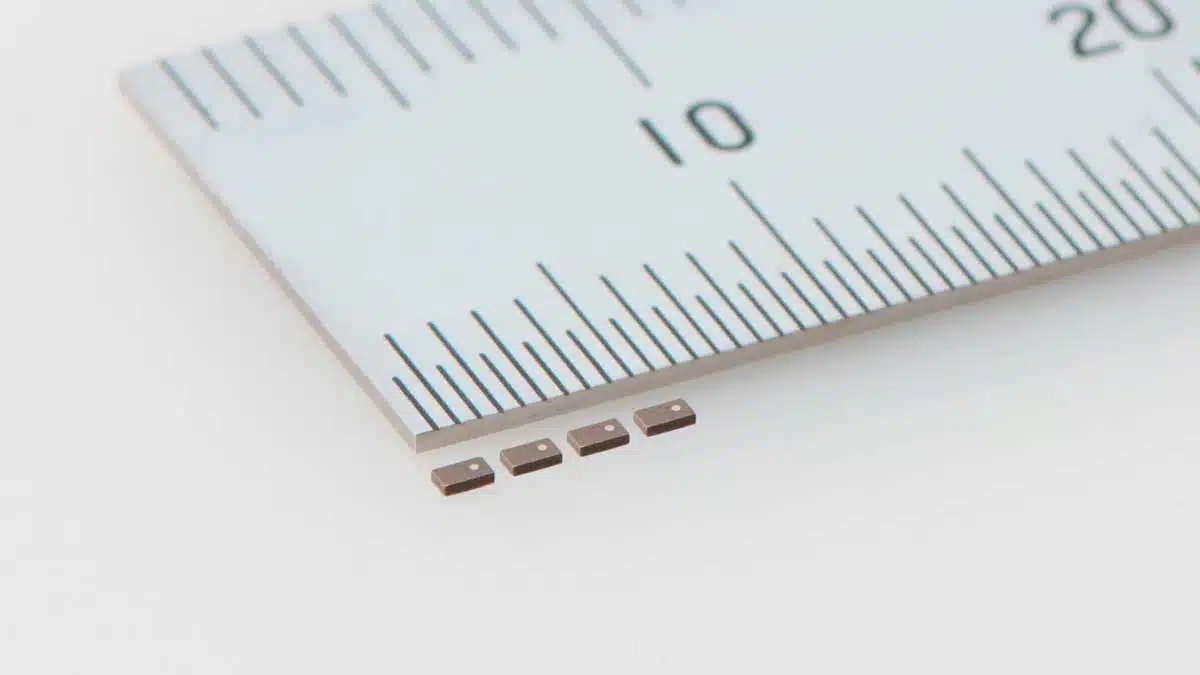
TAIYO YUDEN has begun mass production of a SMD metal power inductor MCOIL™ LSCN series of multilayer thin metal power inductors in dimensions 1.0 x 0.5 x 0.33 mm maximum height.

This power inductor is for use as choke coils in the power supply circuits of wearable devices, such as smartphones, AR/VR glasses, TWS devices, and smart watches. 

RelatedPosts

TAIYO YUDEN Releases 22uF MLCC in 0402 Size for AI Servers

TAIYO YUDEN Releases Compact SMD Power Inductors for Automotive Application

TAIYO YUDEN Expands Multilayer Chip Metal Power Inductors for Smartphones and Wearable Devices

The “LSCND1005CCTR47MH” is 40% lower in height than our previous product, the “LSCNB1005EETR47MB” (1.0 x 0.5 x 0.55 mm), and realizes a metal power inductor as thin as 0.33 mm. This will contribute to the miniaturization and thickness reduction of cutting-edge electronic devices.

Mass production of this products began at our subsidiary, WAKAYAMA TAIYO YUDEN CO., LTD. (Inami-cho, Hidaka-gun, Wakayama Prefecture), in December 2024. Samples are available for 50 yen per unit.

Technology Background
As smartphones, AR/VR glasses, and wearable devices are equipped with higher-performance processors, more sensors, multiple cameras, and higher-capacity batteries for sophistication, electronic components used in them need to be smaller and thinner.

In particular, smartphones are requiring thinner electronic components, due to the trend towards foldable devices that combine large screens and smaller sizes, as well as the adoption of multi-layered circuit boards. On the other hand, wearable devices, such as AR/VR glasses, TWS devices, and smart watches, require smaller, lighter, and thinner components to achieve a thin profile and comfortable fit.

To address these needs, TAIYO YUDEN has been expanding its lineup in the MCOIL™ LSCN series of multilayer metal power inductors which use metallic magnetic core materials with high DC saturation characteristics, and provide superior characteristics for achieving miniaturization and thinness. With our latest upgrade, we have commercialized the “LSCND1005CCTR47MH,” which achieves a thickness of 0.33 mm for a metal power inductor by utilizing the strengths of our multilayer process technology.

In response to market needs, we will continue to expand and improve our product lineup with higher performance and reliability.

■ Application
For use as choke coils for power supply circuits in wearable devices such as smartphones, AR/VR glasses, TWS devices, and smart watches.

■ Characteristics

Part numberSize
(LxW)
[mm]
H
[mm]
max.
Nominal
inductance
[μH]
Inductance
tolerance
[%]
Rated current*3 [A] max.DC
resistance
[mΩ] max.
Saturation
current
Idc1*1
Temperature
rise current
Idc2*2
LSCND1005CCTR47MH1.0×0.50.330.47±20%1.40.8345
  • *1 The saturation current value (Idc1) is the DC current value having an inductance decrease down to 30%. (at 20℃)
  • *2 The temperature rise current value(Idc2) is the DC current value having temperature increase up to 40℃. (at 20℃)
  • *3 The rated current value is following either Idc1(max) or Idc2(max), which is the lower one.

Related

Source: TAIYO YUDEN

Recent Posts

Transformer Safety IEC 61558 Standard

7.11.2025
1

3-Phase EMI Filter Design, Simulation, Calculation and Test

6.11.2025
25

Coilcraft Introduces Ultra-Low Loss Shielded Power Inductors

6.11.2025
13

Exxelia Presents Smart Integrated Magnetics Solution at Space Tech Expo 2025 

5.11.2025
15

Murata Expands High Cutoff Frequency Chip Common Mode Chokes

5.11.2025
9

Transformer Design Optimization for Power Electronics Applications

4.11.2025
21

Bourns Releases High Current Metal Alloy-based, Multilayer Power Chip Inductors

31.10.2025
31

Common Mode Chokes Selection for RF Circuits in Next-Generation Communication Systems

30.10.2025
16

Vishay Releases Space-Grade 150 W 28V Planar Transformers

29.10.2025
29

How to Select Ferrite Bead for Filtering in Buck Boost Converter

23.10.2025
53

Upcoming Events

Nov 11
17:00 - 18:00 CET

Industrial Applications Demand More from Interconnects in Next-Gen Designs

Nov 12
11:00 - 12:00 CET

PCB Design: Impedance is for everyone!

Nov 12
November 12 @ 12:00 - November 13 @ 14:15 EST

Microelectronic Packaging Failure Modes and Analysis

View Calendar

Popular Posts

  • Buck Converter Design and Calculation

    0 shares
    Share 0 Tweet 0
  • Boost Converter Design and Calculation

    0 shares
    Share 0 Tweet 0
  • LLC Resonant Converter Design and Calculation

    0 shares
    Share 0 Tweet 0
  • Flyback Converter Design and Calculation

    0 shares
    Share 0 Tweet 0
  • Ripple Current and its Effects on the Performance of Capacitors

    3 shares
    Share 3 Tweet 0
  • MLCC and Ceramic Capacitors

    0 shares
    Share 0 Tweet 0
  • Dual Active Bridge (DAB) Topology

    0 shares
    Share 0 Tweet 0
  • What is a Dielectric Constant and DF of Plastic Materials?

    4 shares
    Share 4 Tweet 0
  • SEPIC Converter Design and Calculation

    0 shares
    Share 0 Tweet 0
  • Flying Capacitors

    0 shares
    Share 0 Tweet 0

Newsletter Subscription


Passive Components Blog

© EPCI - Leading Passive Components Educational and Information Site

  • Home
  • Privacy Policy
  • EPCI Membership & Advertisement
  • About

No Result
View All Result
  • Home
  • Knowledge Blog
  • PCNS

© EPCI - Leading Passive Components Educational and Information Site

This website uses cookies. By continuing to use this website you are giving consent to cookies being used. Visit our Privacy and Cookie Policy.
Go to mobile version