Passive Components Blog
No Result
View All Result
  • Home
  • NewsFilter
    • All
    • Aerospace & Defence
    • Antenna
    • Applications
    • Automotive
    • Capacitors
    • Circuit Protection Devices
    • electro-mechanical news
    • Filters
    • Fuses
    • Inductors
    • Industrial
    • Integrated Passives
    • inter-connect news
    • Market & Supply Chain
    • Market Insights
    • Medical
    • Modelling and Simulation
    • New Materials & Supply
    • New Technologies
    • Non-linear Passives
    • Oscillators
    • Passive Sensors News
    • Resistors
    • RF & Microwave
    • Telecommunication
    • Weekly Digest

    Bourns Extends Rotational Life Option for its Guitar Potentiometer

    Modeling and Simulation of Leakage Inductance

    Power Inductor Considerations for AI High Power Computing – Vishay Video

    TAIYO YUDEN Releases Compact SMD Power Inductors for Automotive Application

    Fischer Releases High Vibration Robust Ratchet Locking USB-C Connector System

    Littelfuse Unveils High-Use Tactile Switches with 2 Million Cycle Lifespan

    KYOCERA AVX Releases Compact High-Directivity Couplers

    Supercapacitors Emerge as a Promising Solution to AI-Induced Power Energy Spikes

    Wk 18 Electronics Supply Chain Digest

    Trending Tags

    • Ripple Current
    • RF
    • Leakage Current
    • Tantalum vs Ceramic
    • Snubber
    • Low ESR
    • Feedthrough
    • Derating
    • Dielectric Constant
    • New Products
    • Market Reports
  • VideoFilter
    • All
    • Antenna videos
    • Capacitor videos
    • Circuit Protection Video
    • Filter videos
    • Fuse videos
    • Inductor videos
    • Inter-Connect Video
    • Non-linear passives videos
    • Oscillator videos
    • Passive sensors videos
    • Resistor videos

    Modeling and Simulation of Leakage Inductance

    Power Inductor Considerations for AI High Power Computing – Vishay Video

    Coupled Inductors in Multiphase Boost Converters

    VPG Demonstrates Precision Resistor in Cryogenic Conditions

    Comparison Testing of Chip Resistor Technologies Under High Vibration

    EMC Challenges for High Speed Signal Immunity and Low EMI

    MOSFET Gate Drive Resistors Power Losses

    Modified Magnetic Reluctance Equivalent Circuit and its Implications

    Improving Common Mode Noise Reduction while Decreasing BOM

    Trending Tags

    • Capacitors explained
    • Inductors explained
    • Resistors explained
    • Filters explained
    • Application Video Guidelines
    • EMC
    • New Products
    • Ripple Current
    • Simulation
    • Tantalum vs Ceramic
  • Knowledge Blog
  • Suppliers
    • Who is Who
  • Events
No Result
View All Result
Passive Components Blog
No Result
View All Result

Tantalum Capacitor Reliability Estimation Based on Anode Screening

14.7.2022
Reading Time: 6 mins read
A A

Prediction of tantalum capacitor reliability at early stage of manufacturing can considerably save cost and time. Vladimir Azbel in his LinkedIn blog propose a method to predict the capacitor reliability based on tantalum anode assessment.

The reliability of a tantalum capacitor largely depends on maintaining the stability of its leakage currents (DCL), which depends on the intensity of the development of the anode aging process, under the influence of temperature and applied voltage acting on the tantalum capacitor (TC), both during operation and in accelerated Weibull tests, Life Test, burn-in, the time of which varies from tens to several thousand hours. In these tests, the indicator of the anode aging process is the behavior of the DCL TC.

RelatedPosts

Enhanced Process Control in Tantalum Capacitor Anode Manufacturing Reduces Cost and Improves Reliability

Enhancing Effectiveness of Tantalum Capacitor Anode Control

Risk of Tantalum Capacitor Anode Overheating: Modeling and Practical Solutions

Today, there is no test that allows, regardless of TC, estimating breach of the technological process or the acceptability of the anode design, for requirements design TC at the stage of its production. The physical processes leading to the degradation of the DCL TC, taking place, in above mention tests, are due to diffusion processes responsible for the thermal aging of the anode, which leads to non-convertible changes in the microstructure and, accordingly, the mechanical and physical properties of the anode.

The presence of a test, that allows estimating the stability of the DCL TC at the stage of anode production, during 0.5 -1 hour, will allow checking the acceptability of the anode to the design requirements TC, in case of a breach of the production recipe or its calculation, which will reduce time and financial losses.

Figure 1. Tantalum anode material hardness versus grain size chart

As an indicator of the anode aging process, it is proposed to use the approach used in materials science for a heat-resistant material. To assess the intensity development of aging, the value of the difference in yield strength Δσ= σa-σagn of the material is used, before (σa) and after thermal aging (σagn). The smaller this difference, the lower the risk of aging. The yield strength of a material is considered to be the most structurally sensitive parameter of its mechanical properties.

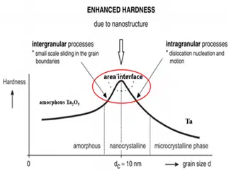
To calculate the yield strength of the anode, model, on-base its structural was proposed. From the materials science point of view, the anode can be considered as a composite material consisting of a sintered porous tantalum pellet, an amorphous Та2О5 oxide film, and an interface region (IR) formed between Ta and the amorphous Та2О5 film. Differences in the mechanical characteristics of the materials included in the anode, see Fig.1 leads to the formation of a gradient of internal stresses, which leads to an increased risk of aging.

The most critical structural region of the anode, which affects the growth of the internal stress gradient, is the formation of a film of amorphous oxide Та2О5, which is accompanied by a phase transformation, which causes an increase in additional uncontrolled internal stresses in its volume.

The yield stress of the anode is represented by the equation:

 σe = Vf*σff + Vt*σym + σi

yield stress porous of matrix (sintered pellet):

σ y (σym) = b* σ 0*(X/D) 2

  • σe – yield stress of anode (composite)
  • σff – fracture strength of amorphous Та2О5
  • σi – strength interface
  • Vf- volume fractions amorphous Та2О5
  • Vt- volume fractions of matrix
  • X – neck size
  • D- primary powder particle, Note: The size D determines BET powder.
  • b is an empirical constant
  • σ 0 is the yield point of the deformed material (without porosity)

According to the proposed anode yield strength model, Δσ = σeagn-σea (σea anode yield strength before and σeagn after thermal aging), reflects the magnitude of internal stresses caused by structural changes in the anode volume, formed as a result of the breach of the production technology or its design calculation. Anode testing time reduction is achieved by accelerating diffusion processes by increasing the aging temperature to 450°C in air, which ensures the availability of free oxygen and accelerates diffusion processes associated with oxygen and vacancies in the anode volume by 3-4 orders of magnitude compared to the testing temperature TC 85-170 °C.

The temperature is 450°C, the maximum allowable aging temperature, in air, which does not lead to the crystallization of amorphous Та2О5 and does not affect the primary porosity and the volume fraction of amorphous Та2О5. Thus, it can be assumed that the temperature of 450°С does not affect the values of σff and σym.

Figure 2. correlation between anode strength and final tantalum capacitors DCL failures

Therefore, using the proposed expression for the yield strength of the anode, taking into account the above, we can Δσ = σiagn– σia, where σia and σiagn, are the components of the anode yield strength due to the contribution of the interface zone, before and after the anode aging at 450°C/air.

At Δσ/σia →0, it means a decrease in the risk of development of the aging process and degradation of DCL.

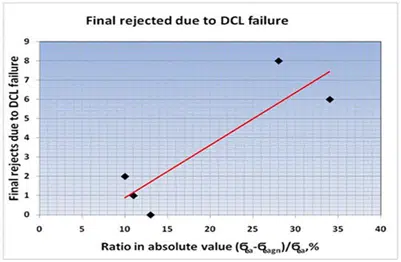
The ratio of the difference between the yield strength of the anode before (σea) and after aging at 450°C 450 ° C (σeagn) to σea. is used to predict the reliability of a tantalum capacitor anode. With an increase in this indicator, one should expect an increase in the number of failures during reliability testing and inversible. The graph in Figure 2. shows a very clear correlation between this ratio, expressed as a percentage, and the number of fails. This test allows you to estimate the acceptability of the anode, for further use for the production of tantalum capacitors.

Tantalum Capacitors Reliability Prediction by Anode Characterization During Manufacturing Process

Related

Source: Vladimir Azbel Blog

Recent Posts

Modeling and Simulation of Leakage Inductance

9.5.2025
2

Supercapacitors Emerge as a Promising Solution to AI-Induced Power Energy Spikes

6.5.2025
39

Murata and NIMS Built New Database of Dielectric Material Properties

5.5.2025
48

Tariffs Crush Sales Sentiment in April 2025 ECST Results

5.5.2025
65

Solid State Polymer Multilayer Capacitors For High Temperature Application

2.5.2025
34

Graphene-Based BOSC Bank Of Supercapacitor Cells

2.5.2025
13

Hybrid Energy Storage System for Nanosatellite Applications

1.5.2025
9

COTS-Plus Bulk Tantalum Capacitor for LEO Flight Platforms

29.4.2025
38

Shielding Cabinets

29.4.2025
18

Magnetic Shielding and Magnetic Shielding Sheets

29.4.2025
28

Upcoming Events

May 14
11:00 - 12:00 CEST

Reliable RIGID.flex PCBs for Critical Applications – Made in Europe

May 14
17:00 - 17:30 CEST

Calculating Foil Winding Losses with AI

May 28
16:00 - 17:00 CEST

Power Over Data Line

View Calendar

Popular Posts

  • Buck Converter Design and Calculation

    0 shares
    Share 0 Tweet 0
  • Boost Converter Design and Calculation

    0 shares
    Share 0 Tweet 0
  • Flying Capacitors Explained

    0 shares
    Share 0 Tweet 0
  • What Electronics Engineer Needs to Know About Passive Low Pass Filters

    0 shares
    Share 0 Tweet 0
  • Flyback Converter Design and Calculation

    0 shares
    Share 0 Tweet 0
  • NTC/PTC Thermistors LTSpice Simulation; Vishay Video Part I

    0 shares
    Share 0 Tweet 0
  • SEPIC Converter Design and Calculation

    0 shares
    Share 0 Tweet 0
  • How to Design High Energy Power Inductor

    0 shares
    Share 0 Tweet 0
  • Ripple Current and its Effects on the Performance of Capacitors

    3 shares
    Share 3 Tweet 0
  • RLC Circuit Switching Response Explained

    0 shares
    Share 0 Tweet 0

Newsletter Subscription


Passive Components Blog

© EPCI - Leading Passive Components Educational and Information Site

  • Home
  • Privacy Policy
  • EPCI Membership & Advertisement
  • About

No Result
View All Result
  • Home
  • Knowledge Blog
  • Premium Suppliers

© EPCI - Leading Passive Components Educational and Information Site

This website uses cookies. By continuing to use this website you are giving consent to cookies being used. Visit our Privacy and Cookie Policy.
Go to mobile version