Passive Components Blog
No Result
View All Result
  • Home
  • NewsFilter
    • All
    • Aerospace & Defence
    • Antenna
    • Applications
    • Automotive
    • Capacitors
    • Circuit Protection Devices
    • electro-mechanical news
    • Filters
    • Fuses
    • Inductors
    • Industrial
    • Integrated Passives
    • inter-connect news
    • Market & Supply Chain
    • Market Insights
    • Medical
    • Modelling and Simulation
    • New Materials & Supply
    • New Technologies
    • Non-linear Passives
    • Oscillators
    • Passive Sensors News
    • Resistors
    • RF & Microwave
    • Telecommunication
    • Weekly Digest

    PCNS 2025 Final Program Announced!

    DigiKey Expands Inventory with Over 32,000 Stocking NPIs in Q2 2025

    YAGEO Offers High-Performance Diplexers for Dual-Band Wi-Fi 6E/7Integration

    European Components Distribution (DMASS) Faces Continued Decline in Q2 2025

    TDK Announced Wide Frequency Automotive Wirewound POC Inductors

    Bourns Released Rugged, High-Power TO-247 Thick Film Resistor

    Bourns Announced Shielded Power Inductor with High Saturation and Low Radiation

    Würth Elektronik Expands MagI³C with Variable Step-Down Modules

    KYOCERA AVX Releases 600MHz Band71 Compact SAW Duplexer

    Trending Tags

    • Ripple Current
    • RF
    • Leakage Current
    • Tantalum vs Ceramic
    • Snubber
    • Low ESR
    • Feedthrough
    • Derating
    • Dielectric Constant
    • New Products
    • Market Reports
  • VideoFilter
    • All
    • Antenna videos
    • Capacitor videos
    • Circuit Protection Video
    • Filter videos
    • Fuse videos
    • Inductor videos
    • Inter-Connect Video
    • Non-linear passives videos
    • Oscillator videos
    • Passive sensors videos
    • Resistor videos

    Switched Capacitor Converter Explained

    Understanding Inductor Dot Markings and Their Application in LTspice

    Accelerating Full Bridge LLC Resonant Converter Design with Frenetic AI

    Understanding Switched Capacitor Converters

    Coupled Inductors Circuit Model and Examples of its Applications

    Inductor Resonances and its Impact to EMI

    Highly Reliable Flex Rigid PCBs, Würth Elektronik Webinar

    Causes of Oscillations in Flyback Converters

    How to design a 60W Flyback Transformer

    Trending Tags

    • Capacitors explained
    • Inductors explained
    • Resistors explained
    • Filters explained
    • Application Video Guidelines
    • EMC
    • New Products
    • Ripple Current
    • Simulation
    • Tantalum vs Ceramic
  • Knowledge Blog
  • Suppliers
    • Who is Who
  • Events
No Result
View All Result
Passive Components Blog
No Result
View All Result

Test Explanations: Exposures

14.9.2021
Reading Time: 3 mins read
A A

Attention now turns to exposures, with examples of thermal, mechanical and environmental exposures.

Temperature Life
Temperature life, or heat aging, exposures drive diffusion controlled reactions which include corrosion and stress relaxation. Our discussion begins with stress relaxation with corrosion to be discussed in a later section. The significance of stress relaxation is that it results in a decrease in contact force. As noted in Section 2.2.1.5 Contact Normal Force Parameters, Equation 2.3, repeated here for convenience,

RelatedPosts

Polymer Materials and Processing

What is RF Connector

Connector Materials and Processes

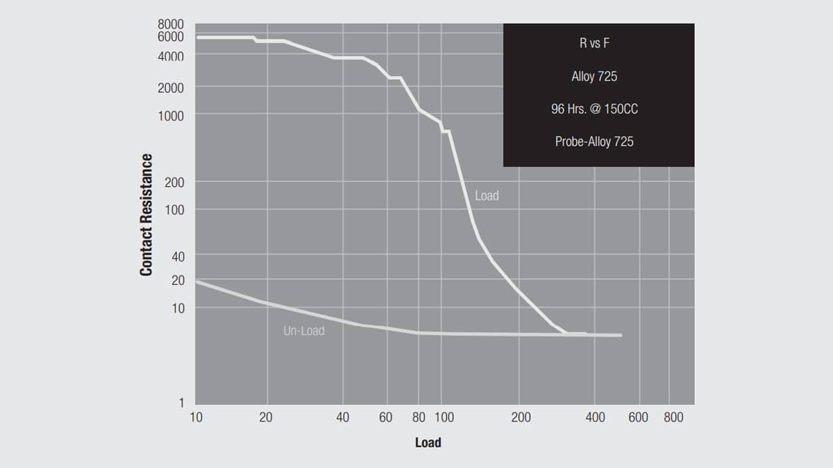
where F is the contact force in a cantilever beam, σ is the stress in the beam and w, t and l are the width, thickness and length of the cantilever beam respectively. So the contact force decreases as stress relaxation reduces the stress in the beam. Recall that, according to Equation 2.10, the contact interface resistance depends inversely on the contact normal force, F, which creates the contact interface area. Consider now Figure 2.102 which shows the contact interface resistance as a function of contact force for both loading and unloading. The loading curve is different from that shown in the main text because it is for a clean metal surface while Figure 2.115 is for a film covered surface, copper alloy 725, a copper-nickel-tin alloy. The initial high resistance region is where film effects are present and the resistance then drops rapidly as the films are disrupted at increased contact force.

Fig. 2.115: Contact interface resistance as a function of contact force: loading and unloading

It is the unloading curve that is of interest in this discussion. Note that the resistance does not change during the initial stages of unloading. This is because the contact area was created at the maximum normal force and is maintained as the force decreases until elastic recovery forces come into play and the contact area does begin to decrease. Generally the contact force reductions due to stress relaxation are of the order of those in the flat section of the unloading curve. Therefore, stress relaxation does not impact the contact resistance directly. Instead, the effect of contact normal force reduction due to stress relaxation comes into play with respect to contact interface resistance in that the mechanical stability of the contact interface is reduced making the interface more susceptible to mechanical disturbance. If the contact interface is disturbed, that is, moves to a new location, the newly created contact interface will be determined by the stress relaxed contact force and, therefore, will be lower than the original contact interface. It is this two-step process, force reduction followed by disturbance that causes the contact resistance to increase as a result of stress relaxation. This is why temperature life is generally a conditioning rather than an exposure.

As noted in Chapter II/2.5.3 Generic Test Plan, however, there is an additional long term effect of stress relaxation in that the loss in contact force is permanent because the contact beams takes a permanent set due to the kinetics of stress relaxation. This means that all subsequent mating of the connector will have a lower deflection and, therefore, a lower contact force than the original connector prior to temperature life conditioning.

When temperature life is used to drive stress relaxation, the temperature and duration of the conditioning is based primarily on the application temperature and life requirements. For example, say an application has an intended life of 5 years (60 months) at an application temperature of 55 °C. Using the doubling every 10 °C rule of thumb, that time/temperature profile can be realized in 2 months at 105 °C (32 x for ΔT of 50 °C and 2 months time). It is important to keep in mind, however, that increases in temperature may bring different degradation mechanisms into play when making such extrapolations. For a twin beam contact the cited acceleration factor may be appropriate, but for a single beam contact latched into a housing, polymer creep may be excessive at the elevated temperature.

Related

Source: Wurth elektronik

Recent Posts

Non-Magnetic Interconnects

23.4.2025
24

10 Tips for Ensuring Reliability of Discrete Wire Assemblies

20.2.2025
54

Polymer Materials and Processing

31.1.2025
47

Basic PCB Technology Overview

1.7.2025
17

What is RF Connector

17.12.2024
9

Creepage and Clearance of Connector

25.7.2025
16

Microwave Multi Line Connectors Mounting and Handling Precautions

17.12.2024
2

BASIC PCB Design Rules – Layout

1.7.2025
29

MEMR RF Relay for Space Compact Redundancy Ring

17.12.2024
3

Connector Temperature Rise and Derating

13.1.2023
22

Upcoming Events

Sep 22
September 22 @ 13:00 - September 25 @ 15:15 EDT

Pre Cap Visual Inspection per Mil-Std-883 (TM 2017)

Sep 30
September 30 @ 12:00 - October 2 @ 14:00 EDT

MIL-Std-883 TM 2010

Oct 17
12:00 - 14:00 EDT

External Visual Inspection per MIL-STD-883 TM 2009

Oct 21
October 21 @ 12:00 - October 23 @ 14:15 EDT

Space and Military Standards for Hybrids and RF Microwave Modules

Nov 4
November 4 @ 12:00 - November 6 @ 14:15 EST

Wirebond Materials, Processes, Reliability and Testing

View Calendar

Popular Posts

  • Buck Converter Design and Calculation

    0 shares
    Share 0 Tweet 0
  • Boost Converter Design and Calculation

    0 shares
    Share 0 Tweet 0
  • Flyback Converter Design and Calculation

    0 shares
    Share 0 Tweet 0
  • LLC Resonant Converter Design and Calculation

    0 shares
    Share 0 Tweet 0
  • What is a Dielectric Constant and DF of Plastic Materials?

    4 shares
    Share 4 Tweet 0
  • Dual Active Bridge (DAB) Topology Explained

    0 shares
    Share 0 Tweet 0
  • Ripple Current and its Effects on the Performance of Capacitors

    3 shares
    Share 3 Tweet 0
  • How to Design an Inductor

    0 shares
    Share 0 Tweet 0
  • MLCC Case Sizes Standards Explained

    0 shares
    Share 0 Tweet 0
  • MLCC and Ceramic Capacitors

    0 shares
    Share 0 Tweet 0

Newsletter Subscription


Passive Components Blog

© EPCI - Leading Passive Components Educational and Information Site

  • Home
  • Privacy Policy
  • EPCI Membership & Advertisement
  • About

No Result
View All Result
  • Home
  • Knowledge Blog
  • Premium Suppliers

© EPCI - Leading Passive Components Educational and Information Site

This website uses cookies. By continuing to use this website you are giving consent to cookies being used. Visit our Privacy and Cookie Policy.
Go to mobile version