Passive Components Blog
No Result
View All Result
  • Home
  • NewsFilter
    • All
    • Aerospace & Defence
    • Antenna
    • Applications
    • Automotive
    • Capacitors
    • Circuit Protection Devices
    • electro-mechanical news
    • Filters
    • Fuses
    • Inductors
    • Industrial
    • Integrated Passives
    • inter-connect news
    • Market & Supply Chain
    • Market Insights
    • Medical
    • Modelling and Simulation
    • New Materials & Supply
    • New Technologies
    • Non-linear Passives
    • Oscillators
    • Passive Sensors News
    • Resistors
    • RF & Microwave
    • Telecommunication
    • Weekly Digest

    Percolation Phenomenon: Degradation of Molded Power Inductors in DC/DC Converters

    Molex Acquires Smiths Interconnect

    Murata Integrates Component Models into Cadence EDA Tools

    Wk 42 Electronics Supply Chain Digest

    Stackpole Introduces Automotive Thick Film Wide Termination Chip Resistors

    September 2025 ECIA US Components Sales Sentiment Continues in Optimism

    Bourns Release Automotive 4-Terminal Shunt Resistors

    Bourns Releases High Inductance Common Mode Choke

    Vishay Releases Automotive TO-220 Case 50W Thick Film Power Resistor

    Trending Tags

    • Ripple Current
    • RF
    • Leakage Current
    • Tantalum vs Ceramic
    • Snubber
    • Low ESR
    • Feedthrough
    • Derating
    • Dielectric Constant
    • New Products
    • Market Reports
  • VideoFilter
    • All
    • Antenna videos
    • Capacitor videos
    • Circuit Protection Video
    • Filter videos
    • Fuse videos
    • Inductor videos
    • Inter-Connect Video
    • Non-linear passives videos
    • Oscillator videos
    • Passive sensors videos
    • Resistor videos

    Percolation Phenomenon: Degradation of Molded Power Inductors in DC/DC Converters

    Connector PCB Design Challenges

    Efficient Power Converters: Duty Cycle vs Conduction Losses

    Ripple Steering in Coupled Inductors: SEPIC Case

    SEPIC Converter with Coupled and Uncoupled Inductors

    Coupled Inductors in SEPIC versus Flyback Converters

    Non-Linear MLCC Class II Capacitor Measurements Challenges

    Percolation Phenomenon and Reliability of Molded Power Inductors in DC/DC converters

    Root Causes and Effects of DC Bias and AC in Ceramic Capacitors

    Trending Tags

    • Capacitors explained
    • Inductors explained
    • Resistors explained
    • Filters explained
    • Application Video Guidelines
    • EMC
    • New Products
    • Ripple Current
    • Simulation
    • Tantalum vs Ceramic
  • Knowledge Blog
  • Suppliers
    • Who is Who
  • PCNS
    • PCNS 2025
    • PCNS 2023
    • PCNS 2021
    • PCNS 2019
    • PCNS 2017
  • Events
No Result
View All Result
Passive Components Blog
No Result
View All Result

The Benefits of Using MLCCs in Converters

12.12.2022
Reading Time: 5 mins read
A A

This application blog from Knowles Precision Devices explains principles of buck and boost converters function and the benefits of using MLCC multilayer ceramic capacitors in these converters.

Product designers working on critical applications requiring electrical power must carefully select components that not only supply the appropriate amount of voltage at the right time, but also help mitigate issues such as voltage ripple, ensure system longevity, and improve component reliability. 

RelatedPosts

Knowles Releases High Q Non-Magnetic X7R MLCCs for Medical Imaging

Knowles Unveils High-Performance Safety-Certified MLCC Capacitors

Knowles Releases Inductors for Mission-Critical RF Applications

Buck and boost converters, which are the two most basic DC-to-DC converter topologies used in power supplies, are critical power supply building blocks that require careful component consideration. While a buck converter steps down a system’s main power supply for use in lower voltage components, boost converters conversely ramp up voltage to a higher value than the input. Buck and boost converters are increasingly being used in switch-mode power supplies (SMPS) for a wide range of important applications such as power delivery networks for military unmanned aerial vehicles (UAVs) and drones, solar panels, electric vehicles, and X-Ray machines. 

Additionally, because of their reliability and simplicity, these converters serve as ideal building blocks for more complicated topologies, including the following:

  • Forward converters
  • Flyback converters
  • Buck-boost converters
  • Half-bridge converters
  • Full-bridge converters
  • ZVT full-bridge converters
  • Push-pull converters

Let’s take a deeper look at the basics of how buck and boost converters work and the components, such as capacitors, inside them. 

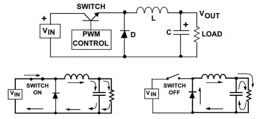
How It Works: The Buck Converter

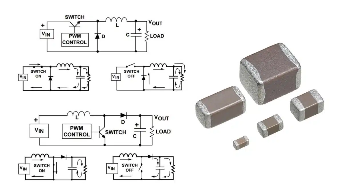
The most common switching converter is the buck converter – see Figure 1., which is used to down-convert a DC voltage to a lower DC voltage of the same polarity. Buck converters are essential in systems that use distributed power rails (like 24 V to 48 V), which must be locally converted to 15 V, 12V, or 5 V with very little power loss. 

During operation, the input voltage is connected to the inductor, and the difference between the input and output voltages is then forced across the inductor, causing current to increase. During this time, the current flows into both the load and the output capacitor, charging the capacitor. When the switch turns off, the capacitor discharges into the load, contributing to the total current – the sum of the inductor and capacitor current – being supplied to the load. 

Figure 1. Buck converter principle
Figure 2. Boost converter principle

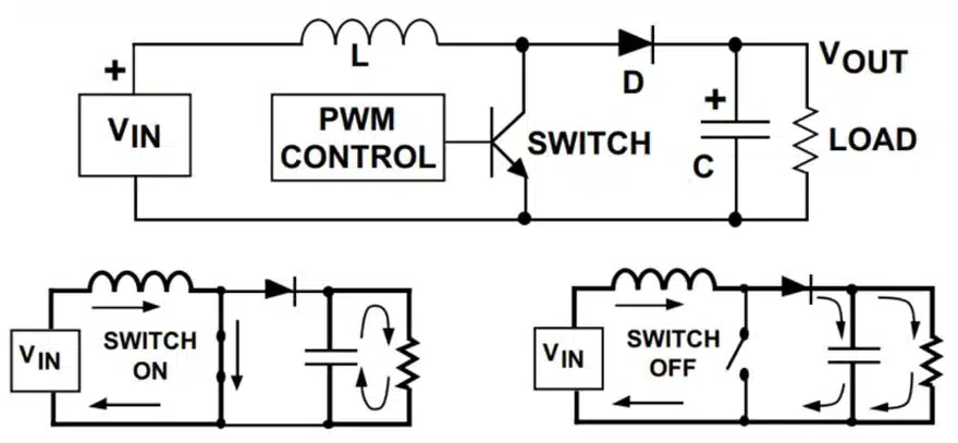
How It Works: The Boost Converter

Conversely, a boost converter – see Figure 2., takes a DC input voltage and produces a DC output voltage that is higher in value than the input, but of the same polarity. When the switch is turned on, the input voltage is forced across the inductor, causing the current to ramp up. When the switch turns off, the decreasing inductor current forces the switch end of the inductor to swing positive, forward biasing the diode and allowing the capacitor to charge up to a voltage that is higher than the input voltage. During steady-state operation, the inductor current flows into both the output capacitor and the load during the switch off time. When the switch is on, the load current is supplied only by the capacitor. 

Why are Capacitors an Important Component in Buck and Boost Converters?

Good engineering practice requires that additional external capacitance be placed at the input and output of all regulators. This is because capacitors not only help reduce voltage ripple and improve reliability, but these components also increase efficiency compared to linear regulators. A well-designed power supply decoupling network will employ different types of capacitors made from different materials such as ceramic, aluminum, and tantalum. 

The Benefits of Using Multilayer Ceramic Capacitors in Converters

Choosing the right capacitor for your converter is a key decision to ensuring your final product is as efficient, durable, and reliable as possible. Multilayer ceramic capacitors (MLCCs) are especially helpful since these capacitors provide several layers in a single component, delivering a capacitance level equivalent to using multiple single-layer capacitor (SLCs) connected in parallel. 

MLCCs can often be used as the following components that may be included in a buck or boost converter:

  • Optional input filters – When the frequency is less than 1MHz, MLCCs can be placed in parallel with either a Bulk Aluminum Electrolytic or Polymer Capacitor for maximized filtering. Meanwhile, when the frequency is greater than MHz, MLCCs are more ideal filters.
  • Bypass capacitors – Eliminates voltage droops on the power supply by storing an electric charge that can be released when a voltage spike occurs.
  • Snubber capacitors – MLCCs help reduce ripple in a switching network.
  • Output capacitors – Low-value ceramic capacitors (<1uF) can be used when the frequency is greater than 1 MHz, or aluminum electrolytic when the frequency is less than 1 MHz.

Using MLCCs in these components can help improve ripple-current rating, filtering performance, and longevity for a converter. MLCCs are versatile and are a good option for anything ranging from a simple topology to the more complicated. 

Special Considerations for High-Reliability Applications

For applications requiring high reliability – for example, a military drone’s power supply – additional testing to military standards (MIL-STDS) must be met. When choosing a capacitor for a high-reliability application, it is important to select components that meet more rigorous MIL-STD requirements including being burnt in at elevated voltage and temperature levels and undergoing 100 percent electrical inspections to ensure conformance with strict performance criteria. This will ensure your components are qualified for use in even the most sophisticated and secure military and aerospace applications. 

Related

Source: Knowles Precision Devices

Recent Posts

Percolation Phenomenon: Degradation of Molded Power Inductors in DC/DC Converters

21.10.2025
4

Murata Integrates Component Models into Cadence EDA Tools

21.10.2025
10

High Energy Density Polymer Film Capacitors via Molecular and Interfacial Design

15.10.2025
25

KYOCERA AVX Expands Stacked MLCC Capacitors Offering

14.10.2025
38

Over-Voltage Protection Clippers, Clampers, Snubbers, DC Restorers

13.10.2025
29

Silicon Capacitors Market: Shaping the Foundation for Next-Gen Miniaturization Electronics

10.10.2025
66

Enhancing Energy Density in Nanocomposite Dielectric Capacitors

9.10.2025
36

Advances in the Environmental Performance of Polymer Capacitors

8.10.2025
66

Vishay Releases DLA Tantalum Polymer Capacitors for Military and Aerospace

8.10.2025
31

Paumanok Releases Capacitor Foils Market Report 2025-2030

7.10.2025
29

Upcoming Events

Oct 20
October 20 - October 23

Digital WE Days 2025 – Virtual Conference

Oct 21
October 21 @ 12:00 - October 23 @ 14:15 EDT

Space and Military Standards for Hybrids and RF Microwave Modules

Oct 28
8:00 - 15:00 CET

Power Up Your Design: SN6507 and the Ready-to-Use Development Kit

View Calendar

Popular Posts

  • Buck Converter Design and Calculation

    0 shares
    Share 0 Tweet 0
  • Boost Converter Design and Calculation

    0 shares
    Share 0 Tweet 0
  • Flyback Converter Design and Calculation

    0 shares
    Share 0 Tweet 0
  • LLC Resonant Converter Design and Calculation

    0 shares
    Share 0 Tweet 0
  • Ripple Current and its Effects on the Performance of Capacitors

    3 shares
    Share 3 Tweet 0
  • What is a Dielectric Constant and DF of Plastic Materials?

    4 shares
    Share 4 Tweet 0
  • SEPIC Converter Design and Calculation

    0 shares
    Share 0 Tweet 0
  • MLCC and Ceramic Capacitors

    0 shares
    Share 0 Tweet 0
  • Dual Active Bridge (DAB) Topology

    0 shares
    Share 0 Tweet 0
  • Flying Capacitors

    0 shares
    Share 0 Tweet 0

Newsletter Subscription


Passive Components Blog

© EPCI - Leading Passive Components Educational and Information Site

  • Home
  • Privacy Policy
  • EPCI Membership & Advertisement
  • About

No Result
View All Result
  • Home
  • Knowledge Blog
  • PCNS

© EPCI - Leading Passive Components Educational and Information Site

This website uses cookies. By continuing to use this website you are giving consent to cookies being used. Visit our Privacy and Cookie Policy.
Go to mobile version