Passive Components Blog
No Result
View All Result
  • Home
  • NewsFilter
    • All
    • Aerospace & Defence
    • Antenna
    • Applications
    • Automotive
    • Capacitors
    • Circuit Protection Devices
    • electro-mechanical news
    • Filters
    • Fuses
    • Inductors
    • Industrial
    • Integrated Passives
    • inter-connect news
    • Market & Supply Chain
    • Market Insights
    • Medical
    • Modelling and Simulation
    • New Materials & Supply
    • New Technologies
    • Non-linear Passives
    • Oscillators
    • Passive Sensors News
    • Resistors
    • RF & Microwave
    • Telecommunication
    • Weekly Digest

    TDK Extends SMT Gate Drive Transformers to 1000 V

    Non-Linear MLCC Class II Capacitor Measurements Challenges

    Researchers Demonstrated HfO Anti-Ferroelectric Flexible Capacitors

    Connector Industry Achieves Double-Digit Growth

    Stackpole Unveils Metal Element High Current Chip Jumpers

    Common Mistakes in Flyback Transformer Specs

    Vishay Releases Miniature SMD Trimmers for Harsh Environments

    Würth Elektronik Releases Push-Button and Main Switches

    Littelfuse Unveils High-Precision TMR Angle Magnetic Sensors

    Trending Tags

    • Ripple Current
    • RF
    • Leakage Current
    • Tantalum vs Ceramic
    • Snubber
    • Low ESR
    • Feedthrough
    • Derating
    • Dielectric Constant
    • New Products
    • Market Reports
  • VideoFilter
    • All
    • Antenna videos
    • Capacitor videos
    • Circuit Protection Video
    • Filter videos
    • Fuse videos
    • Inductor videos
    • Inter-Connect Video
    • Non-linear passives videos
    • Oscillator videos
    • Passive sensors videos
    • Resistor videos

    Non-Linear MLCC Class II Capacitor Measurements Challenges

    Percolation Phenomenon and Reliability of Molded Power Inductors in DC/DC converters

    Root Causes and Effects of DC Bias and AC in Ceramic Capacitors

    How to Calculate the Output Capacitor for a Switching Power Supply

    Switched Capacitor Converter Explained

    Understanding Inductor Dot Markings and Their Application in LTspice

    Accelerating Full Bridge LLC Resonant Converter Design with Frenetic AI

    Understanding Switched Capacitor Converters

    Coupled Inductors Circuit Model and Examples of its Applications

    Trending Tags

    • Capacitors explained
    • Inductors explained
    • Resistors explained
    • Filters explained
    • Application Video Guidelines
    • EMC
    • New Products
    • Ripple Current
    • Simulation
    • Tantalum vs Ceramic
  • Knowledge Blog
  • Suppliers
    • Who is Who
  • Events
No Result
View All Result
Passive Components Blog
No Result
View All Result

TI Buck Regulators with Integrated Capacitors Suppress EMI and Save Board Space

24.8.2022
Reading Time: 4 mins read
A A

Texas Instruments (TI) releases buck regulators with integrated capacitors to suppress EMI and save board space.

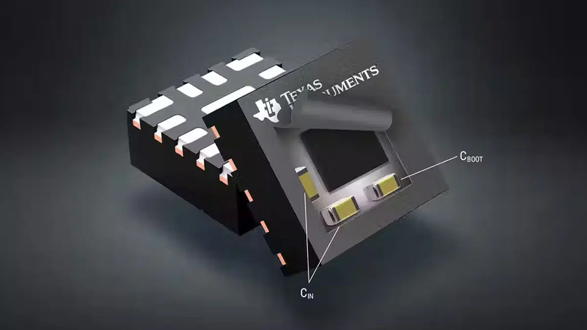
TI rolled out a new pair of synchronous step-down dc-dc converters—the industrial-grade LMQ66430 and automotive-grade LMQ66430-Q1—designed to reduce EMI on factory floors and in medical devices, autos, aerospace, and defense. The 36-V, 3-A buck converters combine two input bypass capacitors with a single boot capacitor in a compact 2.6- × 2.6-mm QFN package with wettable flanks, helping boost power density.

RelatedPosts

TDK Extends SMT Gate Drive Transformers to 1000 V

Non-Linear MLCC Class II Capacitor Measurements Challenges

Researchers Demonstrated HfO Anti-Ferroelectric Flexible Capacitors

“We’re combining IP and in-package innovations. In today’s electric vehicles, you have so many more systems, and these systems are all very sensitive,” he said, including the high-voltage electronics and various power converters, all placed close together in the vehicle. There are also thousands of feet of cabling in electric vehicles, which can lead to large amounts of EMI. “We have to protect these systems from interfering with each other and it’s really complex,” said Carsten Oppitz, VP and GM of buck switching regulators at TI

The Buck Converter Design Challenge

It’s a challenge to create highly efficient and compact designs while also adhering to strict electromagnetic interference (EMI) requirements imposed by groups such as Comité International Spécial des Perturbations Radioélectriques (CISPR). Therefore, component selection becomes a critical part of the design process.

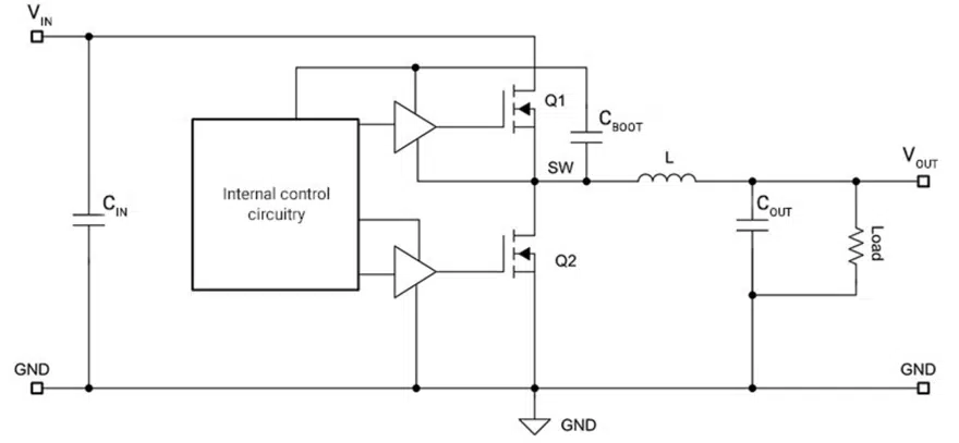
As with most design decisions, choosing between different components almost always comes down to an assessment of tradeoffs based on your most critical design goals. Known for high efficiency and good thermal performance, buck regulators are not typically considered low-EMI options. Fortunately, you have several options for reducing the EMI generated by such regulators. To aid further discussion, Figure 1 shows a simplified buck regulator schematic.

Figure 1: Simplified buck regulator schematic

Board layout considerations

Beyond selecting proper passive component values to ensure a functional design, board layout should be your first consideration when your design must fall under EMI limits. There are two general rules that can help minimize generated EMI with all buck regulator board layouts:

  • Minimize high transient current (di/dt) loop areas by bringing the input capacitor and boot capacitor as close to the VIN and GND pins of the integrated circuit as possible.
  • Minimize the surface area of high transient voltage (dv/dt) nodes by minimizing the area of the switch node.

Integrated input capacitors

As I mentioned, reducing the area of high di/dt current loops is very important when designing switching regulators to remain under EMI limits. In a buck regulator, it’s important to consider the input-voltage-to-ground loop from an EMI perspective. A buck regulator steps down a higher DC voltage to a lower one by switching the connection to the supply on and off, resulting in high-side metal-oxide semiconductor field-effect transistor (MOSFET) (Q1) current, shown in Figure 2.

Figure 2: Input current waveform to a buck regulator

The MOSFET switches on and off rapidly, creating very sharp, almost discontinuous currents supplied by the input capacitor. Some devices, such as TI’s 3-A LMQ66430-Q1 and 6-A LMQ61460-Q1 36-V buck regulators, integrate high-frequency input capacitors inside the package, resulting in the smallest possible input current-loop area. Reducing the area of this input current loop results in smaller parasitic inductance at the input, which reduces the amount of electromagnetic energy emitted.

Integrated boot capacitor

Another high di/dt current loop that you should consider is the boot capacitor loop. The boot capacitor is responsible for supplying charge to the high-side MOSFET gate driver during the on-time. Internal circuitry refreshes this capacitor during the off-time. The source terminal of the high-side MOSFET connects to the switch node rather than GND. Referencing the boot capacitor to the source pin of the MOSFET ensures that the gate-to-source voltage (VGS) is high enough to turn on the MOSFET. With most buck regulators, you will have to leave some switch node area available on the board to connect the bootstrap capacitor, although this can be counterproductive when trying to minimize the area of the switch node for EMI. By integrating the boot capacitor inside the package, the LMQ66430-Q1 follows the two rules that I mentioned earlier, while also reducing the need for an external component.

Conclusion

It can be difficult to design compact power-supply designs capable of remaining under strict EMI limits. Buck regulators with integrated capacitors can make the process of EMI-compliant designs easier, while also helping reduce the overall external component count.

Related

Source: Texas Instruments

Recent Posts

Non-Linear MLCC Class II Capacitor Measurements Challenges

19.8.2025
10

Researchers Demonstrated HfO Anti-Ferroelectric Flexible Capacitors

19.8.2025
7

Common Mistakes in Flyback Transformer Specs

15.8.2025
19

Littelfuse Unveils High-Precision TMR Angle Magnetic Sensors

13.8.2025
9

Stackpole Extends Voltage of High Temp Chip Resistors

13.8.2025
11

High Voltage MLCCs Meeting the Growing Demand for Efficiency in Power Conversion

12.8.2025
94

Radiation Tolerance of Tantalum and Ceramic Capacitors

8.8.2025
69

TDK Releases Compact Polypropylene Film Capacitors for Resonant Topologies

7.8.2025
32

Percolation Phenomenon and Reliability of Molded Power Inductors in DC/DC converters

6.8.2025
40

Root Causes and Effects of DC Bias and AC in Ceramic Capacitors

6.8.2025
54

Upcoming Events

Aug 27
17:00 - 18:00 CEST

Capacitor Assemblies for High-Power Circuit Designs

Sep 3
15:30 - 17:30 CEST

How to Choose Your Magnetic Supplier

Sep 16
17:00 - 18:00 CEST

EMI Shielding Challenges

Sep 22
September 22 @ 13:00 - September 25 @ 15:15 EDT

Pre Cap Visual Inspection per Mil-Std-883 (TM 2017)

Sep 30
September 30 @ 12:00 - October 2 @ 14:00 EDT

MIL-Std-883 TM 2010

View Calendar

Popular Posts

  • Buck Converter Design and Calculation

    0 shares
    Share 0 Tweet 0
  • Boost Converter Design and Calculation

    0 shares
    Share 0 Tweet 0
  • Flyback Converter Design and Calculation

    0 shares
    Share 0 Tweet 0
  • LLC Resonant Converter Design and Calculation

    0 shares
    Share 0 Tweet 0
  • What is a Dielectric Constant and DF of Plastic Materials?

    4 shares
    Share 4 Tweet 0
  • Ripple Current and its Effects on the Performance of Capacitors

    3 shares
    Share 3 Tweet 0
  • Dual Active Bridge (DAB) Topology Explained

    0 shares
    Share 0 Tweet 0
  • How to Design an Inductor

    0 shares
    Share 0 Tweet 0
  • MLCC Case Sizes Standards Explained

    0 shares
    Share 0 Tweet 0
  • MLCC and Ceramic Capacitors

    0 shares
    Share 0 Tweet 0

Newsletter Subscription


Passive Components Blog

© EPCI - Leading Passive Components Educational and Information Site

  • Home
  • Privacy Policy
  • EPCI Membership & Advertisement
  • About

No Result
View All Result
  • Home
  • Knowledge Blog
  • Premium Suppliers

© EPCI - Leading Passive Components Educational and Information Site

This website uses cookies. By continuing to use this website you are giving consent to cookies being used. Visit our Privacy and Cookie Policy.
Go to mobile version