Passive Components Blog
No Result
View All Result
  • Home
  • NewsFilter
    • All
    • Aerospace & Defence
    • Antenna
    • Applications
    • Automotive
    • Capacitors
    • Circuit Protection Devices
    • electro-mechanical news
    • Filters
    • Fuses
    • Inductors
    • Industrial
    • Integrated Passives
    • inter-connect news
    • Market & Supply Chain
    • Market Insights
    • Medical
    • Modelling and Simulation
    • New Materials & Supply
    • New Technologies
    • Non-linear Passives
    • Oscillators
    • Passive Sensors News
    • Resistors
    • RF & Microwave
    • Telecommunication
    • Weekly Digest

    Bourns Unveils Metal Powder Core High Current Low DCR Shielded Power Inductor

    Influence of Tantalum Capacitor Pellets Size on Stability During Oxide Film Formation

    Modelithics Release Discrete Components Optimization Article for RF/Microwave Designers

    Samsung Extends Capacitance of MLCC 0805 X7T 250V to 100nF

    Samtec Releases 800-Position High-Performance Array Connectors  

    DigiKey Announces Back to School Giveaway to Empower Tomorrow’s Innovators

    Ripple Steering in Coupled Inductors: SEPIC Case

    TDK Releases Low Loss Thin-Film Inductors for AI Data Centers

    Samsung Releases Ultra–High-Capacitance 4.7uF 2.5V MLCC in 0201 for AI GPU

    Trending Tags

    • Ripple Current
    • RF
    • Leakage Current
    • Tantalum vs Ceramic
    • Snubber
    • Low ESR
    • Feedthrough
    • Derating
    • Dielectric Constant
    • New Products
    • Market Reports
  • VideoFilter
    • All
    • Antenna videos
    • Capacitor videos
    • Circuit Protection Video
    • Filter videos
    • Fuse videos
    • Inductor videos
    • Inter-Connect Video
    • Non-linear passives videos
    • Oscillator videos
    • Passive sensors videos
    • Resistor videos

    Ripple Steering in Coupled Inductors: SEPIC Case

    SEPIC Converter with Coupled and Uncoupled Inductors

    Coupled Inductors in SEPIC versus Flyback Converters

    Non-Linear MLCC Class II Capacitor Measurements Challenges

    Percolation Phenomenon and Reliability of Molded Power Inductors in DC/DC converters

    Root Causes and Effects of DC Bias and AC in Ceramic Capacitors

    How to Calculate the Output Capacitor for a Switching Power Supply

    Switched Capacitor Converter Explained

    Understanding Inductor Dot Markings and Their Application in LTspice

    Trending Tags

    • Capacitors explained
    • Inductors explained
    • Resistors explained
    • Filters explained
    • Application Video Guidelines
    • EMC
    • New Products
    • Ripple Current
    • Simulation
    • Tantalum vs Ceramic
  • Knowledge Blog
  • Suppliers
    • Who is Who
  • Events
No Result
View All Result
Passive Components Blog
No Result
View All Result

To Be Planar or Not To Be

24.10.2023
Reading Time: 3 mins read
A A

This article based on Chema Molina, CEO of Frenetic newsletter discusses planar magnetics considerations as it may not be the best optimum solution designers are asking for.

The trend of planar magnetics as the holy grail of magnetics has lasted 30 years. The trend consists of people, usually not magnetic experts, asking for a planar solution to improve their power density. Or teams of engineers, only trying to solve their designs with Planar technologies without considering any other option.

RelatedPosts

Common Mistakes in Flyback Transformer Specs

Accelerating Full Bridge LLC Resonant Converter Design with Frenetic AI

How to design a 60W Flyback Transformer

That’s a mistake.

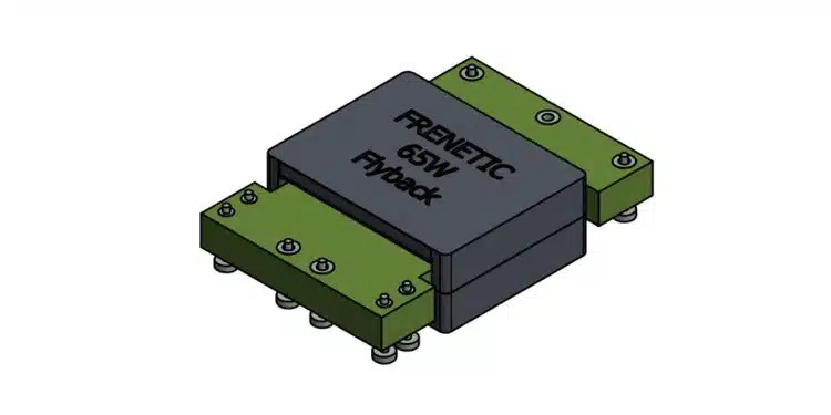
In most cases, the planar solution is not the best, I would say in only 10% of the cases, the planar is the best technical solution for DC/DC magnetics. Inductors are usually the main discussion, so I will focus on transformers and flybacks directly. In the Flyback topology, we have done both cases and to be honest, there was only one case I considered interesting.

When the magnetic is integrated into the PCB from the starting moment. When doing the simulation, you already consider a sizeable parasitic capacitance and use the PCB space considering the winding wires. But in terms of volume, 90% of the cases, you can get a smaller solution and easy to integrate with a concentric magnetic.

For transformers, it depends on the current levels and your mechanical goals. If you consider integrating the magnetic in the PCB, your current levels should be limited to your PCB manufacturer’s copper thickness capability.

For very high current designs, this is entirely different. We don´t use PCB; we use cooper layers and the connection to the power module needs some mechanical solution. Additionally, we use a case to improve the heat dissipation, increasing the weight. In this case, a planar solution is likely more compact.

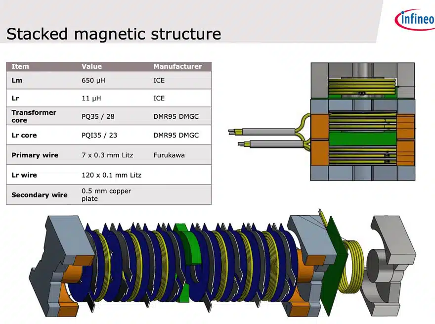
However, once you are not integrated into the PCB, the height can be achieved using Litz or a combination of Litz and Cooper layers. We saw a good example here in this design completed by Antonio Escudero, in my opinion, one of the best engineers of Infineon.

Integrating Transformer + Inductor

One of the limitations of using a planar transformer is the complexity added in integrating the Leakage inductance as part of the operation. The main reasons are:

  • The leakage inductance is low and difficult to predict with more than a 70% accuracy
  • You can include some ferrite layers to increase the leakage like in the Total Component article.

There is a significant benefit of the planar designs in this regard: the repeatability, which is extremely good.

Related

Source: Frenetic

Recent Posts

Bourns Unveils Metal Powder Core High Current Low DCR Shielded Power Inductor

29.8.2025
2

Influence of Tantalum Capacitor Pellets Size on Stability During Oxide Film Formation

29.8.2025
9

Modelithics Release Discrete Components Optimization Article for RF/Microwave Designers

28.8.2025
7

Ripple Steering in Coupled Inductors: SEPIC Case

27.8.2025
10

TDK Releases Low Loss Thin-Film Inductors for AI Data Centers

27.8.2025
10

SEPIC Converter with Coupled and Uncoupled Inductors

26.8.2025
19

Coupled Inductors in SEPIC versus Flyback Converters

26.8.2025
14

TDK Extends SMT Gate Drive Transformers to 1000 V

20.8.2025
21

Non-Linear MLCC Class II Capacitor Measurements Challenges

19.8.2025
44

Researchers Demonstrated HfO Anti-Ferroelectric Flexible Capacitors

19.8.2025
19

Upcoming Events

Sep 3
15:30 - 17:30 CEST

How to Choose Your Magnetic Supplier

Sep 16
17:00 - 18:00 CEST

EMI Shielding Challenges

Sep 22
September 22 @ 13:00 - September 25 @ 15:15 EDT

Pre Cap Visual Inspection per Mil-Std-883 (TM 2017)

Sep 30
September 30 @ 12:00 - October 2 @ 14:00 EDT

MIL-Std-883 TM 2010

Oct 17
12:00 - 14:00 EDT

External Visual Inspection per MIL-STD-883 TM 2009

View Calendar

Popular Posts

  • Buck Converter Design and Calculation

    0 shares
    Share 0 Tweet 0
  • Boost Converter Design and Calculation

    0 shares
    Share 0 Tweet 0
  • Flyback Converter Design and Calculation

    0 shares
    Share 0 Tweet 0
  • LLC Resonant Converter Design and Calculation

    0 shares
    Share 0 Tweet 0
  • What is a Dielectric Constant and DF of Plastic Materials?

    4 shares
    Share 4 Tweet 0
  • Ripple Current and its Effects on the Performance of Capacitors

    3 shares
    Share 3 Tweet 0
  • Dual Active Bridge (DAB) Topology Explained

    0 shares
    Share 0 Tweet 0
  • How to Design an Inductor

    0 shares
    Share 0 Tweet 0
  • Core Materials, Permeability and Their Losses

    0 shares
    Share 0 Tweet 0
  • MLCC Case Sizes Standards Explained

    0 shares
    Share 0 Tweet 0

Newsletter Subscription


Passive Components Blog

© EPCI - Leading Passive Components Educational and Information Site

  • Home
  • Privacy Policy
  • EPCI Membership & Advertisement
  • About

No Result
View All Result
  • Home
  • Knowledge Blog
  • Premium Suppliers

© EPCI - Leading Passive Components Educational and Information Site

This website uses cookies. By continuing to use this website you are giving consent to cookies being used. Visit our Privacy and Cookie Policy.
Go to mobile version