Transformers are magnetic components consisting of two or more inductively coupled windings that transfer energy via a shared core. They are used for galvanic isolation, voltage and current conversion, and impedance matching across a wide range of frequencies. Transformers form, together with inductors and chokes, the core building blocks of magnetic components used in modern electronic systems.
In this article we review key transformer types used in data and telecom interfaces, switched‑mode power supplies and measurement circuits, and highlight the most important parameters and standards for design engineers. The focus is on practical aspects of LAN and xDSL line transformers, PoE and offline power transformers, and current sense transformers, with references to relevant international standards.
Key Takeaways
- Transformers consist of inductively coupled windings and serve for galvanic isolation, voltage conversion, and impedance matching.
- The article reviews key transformer types for data, telecom, and power applications, emphasizing design parameters and international standards.
- Transformers can be classified by function and frequency, impacting their design and application.
- Key parameters like inductance, leakage inductance, and isolation rating dictate transformer performance across different applications.
- Practical design tips focus on meeting manufacturer specifications and regulatory standards for various transformer types.
Transformer basics and classification
Transformers operate on the principle of electromagnetic induction: a time‑varying current in one winding produces a changing magnetic flux in the core, which induces a voltage in other windings. The ratio between primary and secondary voltages is ideally proportional to the turns ratio, while real devices also exhibit leakage inductance, winding resistance and core losses.
From a system perspective, transformers can be classified along several dimensions. By function, we typically distinguish signal and line interface transformers (for Ethernet, DSL, audio), power transformers for switched‑mode power supplies, and current sense transformers for measurement and control. By frequency range, mains transformers operate at 50/60 Hz, SMPS transformers in the tens to hundreds of kHz, and communication transformers from hundreds of kHz into the MHz range.
Across these families, a number of key parameters repeatedly appear in datasheets and application notes. These include inductance, leakage inductance, DC resistance, isolation rating, inter‑winding capacitance, saturation current and, in some cases, linearity metrics such as total harmonic distortion. The relative importance of each parameter depends strongly on the application area, as summarised in Table 1.
| Parameter | Signal / LAN | xDSL line | Power (SMPS) | Current sense |
|---|---|---|---|---|
| Inductance | Medium | High | High | Medium |
| Leakage inductance | High | High | Medium | High |
| DC resistance | Medium | Medium | High | Medium |
| Isolation rating | High | High | High | Medium–High |
| Inter‑winding capacit. | High | High | Medium | Medium |
| THD / linearity | Medium | High | Low–Medium | Medium |
In the following sections, these general concepts are illustrated using concrete families of LAN, DSL, power and current sense transformers.
LAN, Telecom and Power Transformers
The following sections describe typical transformer solutions used in communication interfaces (Ethernet and xDSL) and in power conversion (Flex, PoE and offline mains transformers), as well as current sense transformers for switched‑mode power supplies. While the magnetic principles are shared, each application imposes its own requirements on inductance, isolation, bandwidth and loss distribution.
LAN and LAN RJ45 series Ethernet transformers
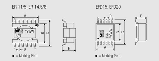
The LAN Ethernet transformers (Figure 1.) are not simple transformers, but rather modules in which, depending on the number of ports for which they are suitable, at least two transformers and a certain number of current-compensated chokes are contained.
As the name denotes, they are designed as transformers for Ethernet networks. Ethernet is the most widespread form of local network (Local Area Network – LAN). Ethernet is operated at different transmission speeds. The requirements for Ethernet are described in the IEEE802.3 standards:
- 10 Base-T: transmission rate 10 Mbps > standard IEEE802.3
- 100 Base-T: transmission rate 100 Mbps > standard IEEE802.3u
- 1000 Base-T: transmission rate 1000 Mbps > standard IEEE802.3ab
- Power over Ethernet: independent of the transmission rate > IEEE802.3af
For these standards, the transmission medium is a copper cable with unshielded, twisted pairs (UTP) of type CAT5 or better. The other IEEE802.3 series standards refer to glass fibre cable transmission.
For 10 Base-T and 100 Base-T, one wire pair is used for the transmission channel (transmit) and one for the reception channel (receive). Two of the four wire pairs in the Cat5 cable remain unused. In the case of 1000 Base-T, all four wire pairs are used in both directions.
According to the EN60950 standard (safety of information technology equipment), Ethernet is classified as a TNV 1 circuit (telecommunication network voltage). It has to be isolated against a SELV circuit (safe extra low voltage). The test voltage stipulated by the standard must be at least 1.5 kV with a test duration of 1 min.
As a result of this isolation voltage, it is essential to use a transformer between the network and the Ethernet terminal device. So two transformers are required for 10/100 Base-T networks and four transformers for 1000 Base-T networks. The necessary number of transformers is integrated in the WE-LAN series modules. As described in the previous section, ring core transformers are used.
To avoid further external components, e.g. current-compensated chokes (data line filters), these are also integrated in the transformer modules (see Figure 2.).
The relevant Ethernet standards for 100 Base-T call for transformers with a minimum inductance of 350 µH and DC current premagnetisation of 8 mA. This should serve to ensure functionality even with small asymmetries of the wire pairs.
The turns ratio is defined by the Ethernet controller used. Whereas 10 Base-T often uses turns ratios of 1 : 1.414 or 1 : 2.5 on at least one of the lines, 100 and 1000 Base-T almost exclusively work with a turns ratio of 1 : 1. This is because the number of secondary turns is so large – due to the high primary inductance combined with a higher number of turns than with 10 Base-T – that they can no longer be accommodated on a small ring core. Winding with twisted wires is also no longer possible, which can still be tolerated for 10 Base-T, but leads to a deterioration in transmission properties for 100 Base-T.
The minimum insertion loss and the maximum values for return loss, cross-talk and common mode rejection are also defined over the entire frequency range.
Telecom Transformers
xDSL Digital Subscriber Line transformers
The xDSL Digital Subscriber Line transformers (Figure 4.) are specialized line interface transformers that are designed to optimise the performance of DSL chipsets. With each chipset varying in power drive levels, impedance characteristics and signal spectrum the transformers are very much chipset dependant in their design.
DSL (Digital Subscriber Line)
DSL technology has its origins in the competition between the telecom and cable television industry to offer each other’s services; video and data services. While the hybrid fiber/coax cable network was already a high-bandwidth network, the telecom industry had to look to some other technology to increase the bandwidth of their aging analog network.
Transformer key parameters in DSL applications
The performance of xDSL transformers is determined by a small set of interacting parameters that must be balanced for each chipset and line standard. Table 2 provides a compact overview before the detailed descriptions that follow
| Parameter | Typical ADSL / VDSL range | Typical HDSL range | Design implications |
|---|---|---|---|
| Inductance | < 100 µH | > 3 mH | Sets low‑frequency cutoff and DC handling. |
| Leakage inductance | Limited to max value | Limited to max value | Affects insertion and return loss. |
| DC resistance | As low as practical | As low as practical | Impacts efficiency and longitudinal balance. |
| Isolation rating | Basic/supplementary, 250 V working per IEC60950 | Same class | Ensures safety between line and SELV. |
| THD | Low, especially for HDSL at high flux density | Critical | Limits permissible drive level and loop length. |
When selecting or designing an xDSL transformer, it is important to start from the IC vendor’s recommended specifications and reference designs, then verify that insertion loss, return loss and longitudinal balance requirements are met over the intended loop length and frequency band.
ADSL (Asymmetrical Digital Subscriber Line)
The ADSL technology formed the backbone of the telecom industry’s initial foray into the high speed data and video services market. Asymmetrical in nature, the ADSL technology reserves the bulk of the available bandwidth for down loading data rather than uploading. This is consistent with the requirements of video services as well as the traffic pattern of the typical internet user. ADSL data rates generally are in the 1 to 16 Mbits/s downstream and 1 to 2 Mbit/s upstream with POTS service concurrently available on the same line. Various flavours and generations of ADSL are, and have been, promoted such as ADSL2, ADSL2+, ADSL+, RADSL, etc.
HDSL (High-Speed Digital Subscriber Line)
Following on the heels of ADSL technology was HDSL which addresses the needs of those users requir ing a symmetrical service with as much bandwidth available for upstream data traffic as downstream. The HDSL services are targeted to service providers, businesses and Small Office Home Office (SOHO) customers. Generally speaking the HDSL technology is a replacement for the older T1/E1 technology. Like ADSL, the HDSL technology is promoted in a host of variants such as SHDSL, SDSL, HDSL-2, HDSL-4 MDSL, IDSL, g.SHDSL etc.
VDSL (Very High Speed Digital Subscriber Line)
The latest generation DSL technologies are the VDSL and VDSL2 technologies. VDSL and VDSL2 increases the maximum available download bit rate to over 100 Mbit/s at short loop lengths. VDSL technologies allow for either symmetric or asymmetric access and support high bandwidth applications such as HDTV in addition to telephone and data services.
Transformer Key Parameters
Inductance:
Inductance requirements vary widely between not only DSL technologies, but also between chipsets. ADSL and VDSL inductance requirements can be below 100 µH while HDSL inductance specifications are over 3 mH. Depending on the specific requirements of the chipset this inductance can be any value in between and is almost always toleranc ed to a level of ± 5 to 10 percent. The inductance specification is almost always specified by the IC manufacturer and is dependant on a host of conflicting requirements including:
- The transformer’s need to handle DC current
- Whether or not the transformer has to perform a filtering function for concurrent POTS operations
- Signal bandwidth
- The insertion loss
- The return loss characteristics
- The impedance characteristics of the chipset
Leakage inductance:
Leakage inductance requirements are almost always held to a maximum value. In rare instances where the chipset is particularly sensitive to variations in impedance, the leakage inductance will be held to a tolerance requirement. While this is possible to achieve, it does result in a design that is very susceptible to variations in manufacturing and should be avoided if at all possible. Factors that dictate the leakage inductance specification include:
- The insertion loss requirements
- Signal bandwidth
- The return loss characteristics required
- The impedance characteristics of the chipset
DC resistance:
Besides affecting the power transfer efficiency of the transformer, DCR resistance also affect to a lesser degree these DSL line transformer requirements:
- The insertion loss requirements
- The return loss characteristics
- The impedance characteristics of the chipset
- Longitudinal balance
Crosstalk:
While crosstalk is always a concern for IC manufacturers, it is typically not an issue with the line interface transformers. Almost all line interface transformers for DSL are constructed on some EP style of core which is by virtue of its’ shape, self shielding.
Voltage/safety isolation:
Voltage/safety isolation is always a consideration as it is the primary purpose of the DSL line interface transformer in the first place. Depending on the safety agency requirements and intended application the isolation as well as creepage and clearance requirements for the transformer will vary. Typically transformers need to supply basic or supplementary isolation for a working voltage of 250 V per the IEC60950 standard. In summary each of these parameter affect the others to a greater or lesser degree. The crux of DSL line interface design is balancing all of these parameters to create a solution that meets the customer requirements in a cost effective manner.
DC current handling:
Typically only HDSL type technologies require the transformer to operate with a DC current applied through the transformer. This requirement is due to the fact that HDSL type equipment is often called on to provide power to remote terminal devices. Typical DC current requirements for HDSL products are 60 to 100 mA.
Turns ratio:
Turns ratios, like inductance, can vary greatly from chipset to chipset. While most transformers have a single primary and secondary winding, it is not uncommon for some chipsets to require separate secondary windings for transmit and receive or even a separate auxiliary winding. Factors affecting the turns ratio include:
- The architecture of the chipset
- The return loss characteristics required
- The impedance characteristics of the chipset
- Whether or not the signal voltage needs to be stepped up or down
Inter-winding capacitance:
Inter-winding capacitance may or may not be specified by the IC manufacturers when defining the transformer requirements depending on the transceivers sensitivity to capacitance. However, regardless of whether or not it is specified, inter-winding capacitance affects the overall performance and is typically limited by the following requirements:
- The insertion loss
- Signal bandwidth
- The return loss characteristics
- The impedance characteristics of the chipset
- Longitudinal balance
Total harmonic distortion:
General: The total harmonic distortion THD denotes the ratio of the effective value of all harmonics of a signal to the effective value of the total signal.
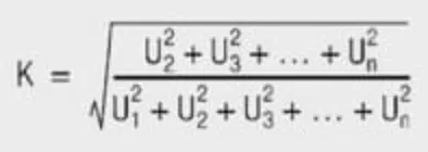
For sinusoidal signals, the total harmonic distortion is used as a measure of non-linear distortions! The smaller the THD, the more the signal corresponds to the original!
Total harmonic distortion is a measure of how much the DSL transformer will distort the desired signal. The harder a transformer is driven, the more the core approaches saturation. As the core approaches saturation the signal begins to distort. While total harmonic distortion is a concern for all DSL transformer, it is not as critical for VDSL transformers where the operation of the core is at higher frequency; hence a lower flux density and further away from saturation. HDSL transformers however utilize the lower end of the frequency bandwidth quite extensively and are often driven quite hard at these frequencies for longer loop lengths. This results in a need for good total harmonic distortion characteristics at a high flux density level.
Practical design tips for DSL transformers
- Start from the line interface IC manufacturer’s reference transformer specification and evaluation board schematics.
- Verify insertion loss and return loss against the appropriate xDSL mask over the full operating frequency band.
- Check that the isolation rating and creepage/clearance satisfy the target safety standard and working voltage.
- Evaluate THD under worst‑case drive conditions, especially for HDSL‑type applications with long loop lengths.
Power Transformers
Power FLEX transformers
The FLEX transformers (Figure 5.) are especially well suited for DC-DC converters in the lower power rang. As a result of their winding structure, consisting of six individual windings each with the same number of turns, as well as the various air gaps available, the Flex transformers are very flexible in their application. When using FLEX transformers in DC‑DC converters, a simple loss budget helps to size the transformer correctly.
| Application | Copper loss share | Core loss share | Notes |
|---|---|---|---|
| Low‑power flyback (<20 W) | 40–60% | 40–60% | Aim for similar Cu and core loss |
| PoE flyback | 30–50% | 50–70% | Check at max PoE class power |
| Auxiliary/housekeeping | 50–70% | 30–50% | Core often under‑utilized |
These percentages are indicative only, but they give a starting point when reading core‑loss curves and estimating winding losses. If one category dominates strongly, consider changing core size, material or winding strategy.
Loss budgeting in SMPS transformers
In flyback and similar SMPS topologies the transformer loss budget is typically divided between copper and core losses, with both contributing significantly to efficiency and temperature rise. A balanced design avoids excessive core losses at high frequency and excessive copper losses at high current, and often targets comparable contributions from both.
When reading core‑loss curves and estimating winding losses, the indicative percentages in Table 3 help to decide whether a different core size, material or winding strategy is required. If one loss category dominates strongly, options include changing the core material, increasing core cross‑section, or optimising the winding arrangement and copper thickness.
The following table shows an example of different sizes.
The appropriate connections wiring of the windings on the circuit board allows various inductance and transformers with different turns ratios to be generated (Figure 7.).
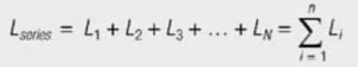
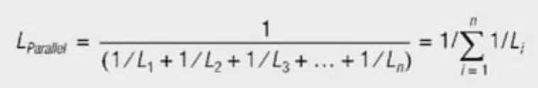
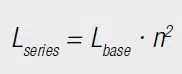
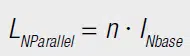
When calculating the resulting currents and inductance, it must be kept in mind that the six windings are wound on the same core – so they are magnetically coupled. Connecting two discrete inductance in series, the inductance are added (Equation [1]). Connected in parallel, the reciprocal values of the inductance add together (Equation [2]), i.e. connecting two equal inductance in parallel produces half the inductance.
Connecting windings to a common core means adding the number of turns. These are squared in the calculation of the resulting inductance. As the number of turns of the single windings for WE-FLEX is identical, the resulting inductance is proportional to the square of the number of windings connected in series (Equation [3]). For parallel connection, the number of turns stays the same; only the conductor cross-section changes. So with parallel connection there is no change in inductance (Equation [4]).

| Connection configuration | Inductance vs single winding (Lbase) | Total available current vs Isatbase | Typical use case |
|---|---|---|---|
| 1 winding in use | 1× | 1× | Small flyback, auxiliary. |
| 2 windings in series | 4× | 1× total, 0.5× per winding | Higher inductance, lower current. |
| 3 windings in series | 9× | 1× total, ≈0.33× per winding | High inductance, low current. |
| 2 windings in parallel | 1× | 2× total | Higher current at same L. |
| 3 windings in parallel | 1× | 3× total | High‑current paths. |
These relationships follow directly from the way turns are added in series and conductor cross‑section is increased in parallel on a shared core.
Lbase Inductance of a Winding
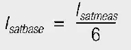
To determine Isatbase all six windings were connected in parallel and the inductance measured as a function of current. The saturation current determined in this way is the total saturation current of the component. Isatbase is then the measured saturation current divided by six.
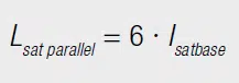
Consequently, the total saturation current of the transformer is six times Isatbase. This total saturation current can now be distributed over the current-carrying windings. If, for example, three windings are connected in series, the six times Isatbase can be distributed over these three windings. Hence, each of these windings may carry current of twice Isatbase.
In the case of parallel connection of three windings, these can also carry twice Isatbase. For parallel connection, the individual currents add together to produce the total current, six times Isatbase. The following rules generally apply:
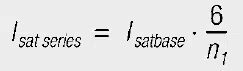
nI Number of Current-Carrying Windings
In contrast, the rated current, which is a property of the wire diameter, cannot be distributed to other windings. The resulting rated current for series and parallel connections is given by the following formulas:

The saturation current is not crucial when it comes to dimensioning transformers as forward converters or push-pull converters, but rather the voltage-µs product. The voltage-µs product or Volt-µs product is proportional to the number of turns, so that the Volt-µs product from has to be multiplied by the number of windings connected in series.
The windings of the FLEX transformers are tested against each other with 500 VDC. There is no additional insulation layer between the individual windings, so they can only be used in the low voltage range (SELV: < 60 VDC).
PoE Series Power-over-Ethernet Transformers
A DC-DC converter is also required for the power supply in Power over Ethernet. This has to satisfy the following tasks:
- PoE dialogue for detection and power classification
- Voltage regulation to the required output voltage
- Isolation of 1.5 kVAC in accordance with EN60950
Only a DC-DC converter with a transformer meets the isolation requirement. The leading semiconductor manufacturers have developed ICs that implement both the PoE dialogue, as well as voltage regulation. Examples of these include LTC4267 (Linear Technology), LM5071 (National Semiconductor) and TPS23750 (Texas Instruments). These ICs were developed for flyback converters with switching frequencies of between 200 und 400 kHz.
Compared with pure LAN magnetics, PoE transformers must handle both data‑related requirements and the additional constraints of power transfer at the specified PoE class. While LAN transformers focus primarily on bandwidth, insertion loss and common‑mode rejection, PoE flyback transformers must also meet isolation requirements, volt‑µs constraints and thermal limits at the maximum delivered power.
The transformers are tested with 1.5 kVAC between the primary and secondary sides and therefore comply with the international standards EN60950 and IEC60950.
UNIT offline transformers
The UNIT transformers (Figure 9.) are designed for worldwide mains input voltages. The input voltage can span the range from 85 VAC (e.g. Japan) to 265 VAC (e.g. Germany). In contrast to 50 Hz transformers, which have to be switched from 110 V to 230 V, the modern switch mode power supplies regulate this. At the same time optimized IC switching regulators are available and make the requests for low standby losses possible.
A switched DC voltage of 120 V to 385 V is applied at the transformer. Many IC manufacturers have brought ICs in the low power range onto the market in which MOSFETS are already integrated. Consequently the circuit complexity and the amount of external components is minimized.
In low‑power offline applications, these transformers are typically used in flyback or quasi‑resonant topologies that operate from a rectified mains bus. Besides electrical parameters such as inductance and volt‑µs capability, designers must pay close attention to isolation ratings, insulation systems and creepage and clearance distances to comply with safety standards.
CST Current Sense Transformers
Current sense transformers are used in switched‑mode power supplies to sense primary current for current‑mode control and over‑current protection without incurring the losses associated with high‑value series sense resistors. They provide galvanic isolation between the power stage and the control circuitry and can offer high bandwidth and accuracy when correctly dimensioned.
There are two modes of regulating the output voltage of a switched mode power supply. For voltage regulation (Voltage Mode, VM), the output voltage is measured directly and compared with a “reference voltage”. For current regulation (Current Mode, CM), the primary current is measured. The output voltage serves as a reference here.
To measure the primary current, the voltage can be tapped by a sense resistor. A current converter is often used for a higher primary current so that losses are not too high. The current is then determined with a burden resistor RT by measuring voltage (Figure 11).
The voltage measured at RT is given by:
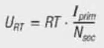
- URT = voltage at the burden resistor
- RT = burden resistor

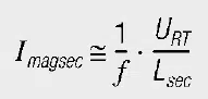
As described in the functionality of a transformer, a magnetizing current also appears here. This affects the result as a measurement error. The magnetizing current must therefore be considered when selecting a current converter. It can be estimated with the following formula:
This is clarified with an example:
A current converter with the following properties is sought:
- Input currents: Ii = 1 A–5 A
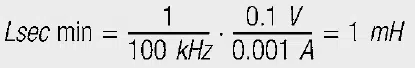
- Frequency: f = 100 kHz
- Burden voltage: URT = 0.1 V at 1 A = 0.5 V at 5 A
- Accuracy: 10%
For a turns ratio of 1 : 100, Equation [6] gives a burden resistance of 10 Ω. The accuracy for the input current of 1A should be better than 0.1 A, i.e. the magnetizing current carried over to the secondary side must be smaller than 0.001 A. Equation [8] calculates the minimum inductance as:
Key parameters when selecting a current sense transformer
- Turns ratio: sets the relationship between primary current and secondary current, and therefore the sense voltage across the burden resistor.
- Burden resistor: determines the conversion gain and power dissipation, and must be chosen so that the resulting sense voltage matches the controller requirements.
- Magnetizing inductance: influences low‑frequency accuracy by limiting the fraction of primary current that is transformed into the secondary.
- Isolation rating: defines the safe voltage separation between primary and secondary circuits.
When selecting a CST, check that the core does not saturate at the maximum peak current, that the magnetizing current error is acceptable over the full operating frequency range, and that the isolation rating, creepage and clearance meet the applicable safety standard.
How to select the right transformer type for your application
- Step 1 – Define the application and signal type
Determine whether your design is for data/telecom interfaces, power conversion, or current measurement, and note voltage levels, frequencies, and required isolation so you can narrow the transformer family (LAN/DSL, power, PoE, offline, current sense).
- Step 2 – Identify relevant standards and IC requirements
Check which standards apply (for example IEEE 802.3 for Ethernet, ITU‑T G.99x for DSL, IEC 62368‑1 for safety) and review the reference designs and recommended transformer specifications from your PHY, modem or controller IC vendor.
- Step 3 – Select the appropriate transformer family
Choose a LAN or xDSL line transformer for communication over twisted‑pair lines, a FLEX or PoE transformer for isolated DC‑DC or PoE power conversion, a UNIT offline transformer for direct mains‑connected SMPS, or a current sense transformer for isolated current measurement in power converters.
- Step 4 – Check key electrical parameters
For the chosen family, verify inductance, leakage inductance, DC resistance, isolation rating, inter‑winding capacitance, saturation current and, where relevant, total harmonic distortion against the limits defined by your standard and IC reference design.
- Step 5 – Consider mechanical, thermal and safety constraints
Confirm that the package, creepage and clearance distances, isolation voltage and temperature rise of the transformer suit your PCB layout, ambient conditions and applicable safety requirements, especially in PoE and offline mains designs.
- Step 6 – Prototype and validate performance
Build a prototype using the selected transformer and measure the relevant performance metrics: for communication transformers, check insertion and return loss and longitudinal balance; for power transformers, confirm efficiency, regulation and thermal behaviour; for current sense transformers, verify accuracy and response under worst‑case operating conditions.
Conclusion
Although LAN, xDSL, PoE, offline and current sense transformers all rely on the same magnetic principles, each family is optimised for a different trade‑off between bandwidth, loss, isolation and linearity. Understanding how datasheet parameters such as inductance, leakage inductance, DC resistance, isolation rating, inter‑winding capacitance and THD relate to system‑level requirements is essential for robust designs.
For communication interfaces, this means matching transformer characteristics to standard‑defined masks for insertion loss, return loss and longitudinal balance, while simultaneously meeting isolation requirements. In power applications, careful loss budgeting, correct use of volt‑µs limits and respect for thermal and safety margins determine efficiency and reliability.
FAQ
A transformer consists of two or more inductively coupled windings on a shared core and is used for galvanic isolation, voltage or current conversion, and impedance matching between circuits.
Transformers are commonly classified by function into signal and line interface transformers, power transformers for switched‑mode power supplies, and current sense transformers, and by frequency into mains (50/60 Hz), SMPS (tens to hundreds of kHz) and communication (hundreds of kHz to MHz) types.
Key parameters include inductance, leakage inductance, DC resistance, isolation rating, inter‑winding capacitance, saturation current and, in some applications, total harmonic distortion, each with different importance depending on the application.
LAN Ethernet transformer modules are used whenever an Ethernet PHY is connected to copper twisted‑pair cabling, to provide isolation, impedance matching, and integrated common‑mode chokes that help meet IEEE 802.3 requirements.
xDSL transformers are tightly matched to specific chipsets and DSL standards, balancing inductance, leakage, DC resistance, isolation and THD to meet insertion‑loss, return‑loss and longitudinal‑balance masks over defined loop lengths.
FLEX transformers offer multiple identical windings that can be combined in series or parallel to realise different inductances and turns ratios, enabling flexible use in various low‑power DC‑DC converter topologies.
PoE transformers must handle both data and power; in addition to meeting bandwidth and common‑mode rejection requirements, they must provide sufficient isolation, volt‑µs capability and thermal performance at the specified PoE class power.
UNIT offline transformers are designed for worldwide mains input and are used in low‑power offline switch‑mode power supplies, where they must satisfy isolation, creepage and clearance requirements while operating from a rectified mains bus.
A current sense transformer is preferred when primary currents are high and shunt losses would be excessive, allowing isolated current measurement with lower dissipation and good bandwidth for current‑mode control and protection.
Ethernet designs reference IEEE 802.3, DSL designs use ITU‑T G.992.x/G.991.2/G.993.x, and safety aspects are governed by IEC 62368‑1 (and legacy IEC 60950) for information and communication technology equipment.
References
- IEEE 802.3 Ethernet standard series (various parts for 10Base‑T, 100Base‑TX, 1000Base‑T and PoE). https://standards.ieee.org/ieee/802.3/7423/
- ITU‑T Recommendations for digital subscriber line systems, including G.992.x ADSL, G.991.2 SHDSL and G.993.x VDSL. https://www.itu.int/rec/T-REC-G/en
- IEC 60950 / IEC 62368‑1 Safety standards for information technology and communication equipment.
IEC 60950‑1 (withdrawn, historical): https://webstore.iec.ch/publication/5965
IEC 62368‑1 (replacement): https://webstore.iec.ch/publication/75835 - Manufacturer application notes and datasheets for LAN, DSL, PoE, offline and current sense transformers, e.g. Würth Elektronik WE‑LAN, WE‑DSL, WE‑FLEX, WE‑UNIT and WE‑CST series.https://www.we-online.com/en/components/products/capacitors/inductors-transformers
- L. Dixon and other classic SMPS magnetics design notes discussing core selection, volt‑µs limits and loss budgeting in high‑frequency transformers.
Example collection (TI Power Supply Design Seminars): https://www.ti.com/tool/SLUP-SERIES