




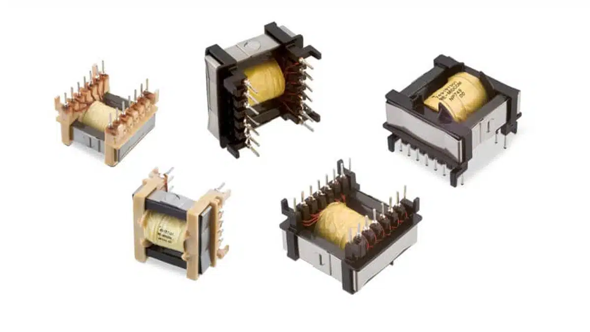
Transformers are magnetic components consisting of two or more inductively coupled windings that transfer energy via a shared core. They are used for galvanic isolation, voltage and current conversion, and impedance matching across a wide range of frequencies. Transformers form, together with inductors and chokes, the core building blocks of magnetic components used in modern electronic systems.
Transformer types differ according to whether they transfer communication signals, convert power or measure current. This article explains the operating principles, selection parameters and practical limits of LAN and xDSL transformers, configurable DC-DC magnetics, PoE and offline power transformers, and current-sense transformers for design, component and purchasing engineers.
Key Takeaways
Select a transformer against its complete operating conditions, not its turns ratio or nominal inductance alone.
- Signal transformers require adequate bandwidth, insertion loss, return loss, balance and linearity under the specified source, load and bias conditions.
- Power transformers require topology-specific checks of winding volt-seconds, reset, peak and RMS currents, core loss, AC winding loss and temperature rise.
- PoE-capable Ethernet magnetics carry data and accommodate DC in their cable-side winding connections; the separate PoE DC-DC transformer converts power and does not carry Ethernet data.
- Series-connected windings on a common core do not follow the same inductance rules as uncoupled inductors. Saturation-current and thermal-current ratings must also be treated separately.
- Current-sense transformers require a defined burden and adequate reset. Switching frequency alone is insufficient to determine pulse-measurement accuracy.
- A dielectric withstand test is not a continuous working-voltage rating or proof of complete equipment safety compliance.
Transformer types: basics and classification
A transformer couples winding circuits through changing magnetic flux. Depending on its construction and application, it can transform voltage, current or impedance and provide galvanic separation. This article concentrates on electronic transformers; mains-frequency and utility transformers are included only as context.
In a conventional transformer, changing core flux induces a voltage in every winding that links that flux. Ideally, the induced voltage ratio follows the turns ratio, while the load-current ratio is inverse. Practical devices also have finite magnetising inductance, leakage inductance, winding resistance, capacitance and core loss. Separate windings provide galvanic separation, but the intended insulation function must be established from the component construction and application requirements.
By function, useful categories include signal and line-interface transformers, power-conversion transformers, pulse and gate-drive transformers, and current transformers. By operating conditions, mains-frequency devices, switched-mode power magnetics and broadband communication transformers present very different design problems. Frequency ranges overlap and should not be used as rigid classification boundaries.
A flyback magnetic component deserves a specific distinction: it intentionally stores energy in its magnetising inductance and transfers that energy during another part of the switching cycle. It is therefore commonly described as a flyback transformer, but its magnetic design is that of a coupled energy-storage inductor rather than a transformer intended mainly for simultaneous power transfer. [1]
The underlying relationships are developed in the article on transformer operating principles, winding volt-seconds and magnetic coupling. Table 1 summarises how the same datasheet parameters lead to different selection priorities.
| Parameter | Signal and LAN | xDSL line | Power conversion | Current sense |
|---|---|---|---|---|
| Magnetising inductance | Low-frequency loading and pulse fidelity | Chipset impedance and lower-band performance | Excitation current, energy storage or resonant behaviour | Excitation-current error and pulse droop |
| Leakage inductance | Upper-band response and matching | Insertion loss and return loss | Commutation, overshoot, clamps or intentional resonance | Rise time and transient response |
| Winding resistance | Attenuation and balance | Loss, impedance and longitudinal balance | Conduction loss and heating | Burden error and heating |
| Insulation system | Interface separation and safety | Line-to-equipment separation | Required working voltage and insulation function | Primary-to-measurement-circuit separation |
| Capacitance | Bandwidth and common-mode coupling | Balance and high-frequency response | Common-mode current, resonance and switching behaviour | Bandwidth, ringing and reset |
| Core nonlinearity | Distortion and bias sensitivity | Distortion at the specified drive level | Saturation margin and waveform-dependent loss | Accuracy, saturation and recovery |
These parameters interact. More turns can increase inductance but also increase conductor length and parasitic capacitance. Closer winding placement can reduce leakage while increasing capacitive coupling. The objective is a suitable combination, not independent minimisation or maximisation of every parameter. [1]
LAN, telecom and power transformers
Communication transformers must preserve a specified signal while meeting interface isolation and electromagnetic-compatibility requirements. Power transformers must additionally handle the converter’s voltage and current waveforms without excessive heating or saturation. The following examples retain the original LAN, DSL, FLEX, PoE, offline and current-sense families, while distinguishing product-family features from universal transformer rules.
LAN and RJ45-integrated Ethernet transformers

LAN magnetics can combine isolation transformers, centre taps and common-mode chokes in one package. Other products provide only part of that network. Check the actual internal schematic rather than assuming that every package contains the same filtering or termination components.
For the conventional copper interfaces discussed here, 10BASE-T carries 10 Mbit/s, 100BASE-TX carries 100 Mbit/s and 1000BASE-T carries 1 Gbit/s. The familiar 10BASE-T and 100BASE-TX arrangements use two pairs for data, whereas 1000BASE-T uses all four pairs bidirectionally. Pairs unused for data are not necessarily unused electrically: they may carry PoE power.
IEEE 802.3 covers many physical layers, including additional copper and optical interfaces. The two-pair and four-pair arrangements above should not be extended to every Ethernet variant. Specify the exact PHY, data rate, cable construction and channel requirements before selecting magnetics.

The transformer and any common-mode choke perform different functions. The transformer couples the differential signal across the isolation boundary. A common-mode choke impedes unwanted common-mode current while permitting the intended differential signal. Their placement, centre-tap connections and interaction with the PHY must follow the interface design.
As a concrete specification example, Würth Elektronik part 7490220120 specifies a minimum inductance of 350 µH measured at 100 kHz and 100 mV with 8 mA bias, a 1:1 turns ratio, and a minimum 1500 V RMS insulation test for 1 min. These are documented conditions for that component, not a substitute for checking the selected PHY’s requirements or the complete interface standard. [2]
Open-circuit inductance must remain adequate at the relevant bias and temperature. PoE current imbalance, winding resistance imbalance and the selected centre-tap arrangement can affect magnetic operating margin. A PoE designation must therefore be read together with the permitted current per centre tap or winding, temperature limits and the exact supported configuration. [2, 3]

The turns ratio is selected for compatibility with the PHY’s driver and receiver architecture. Do not select it from data rate alone. An integrated RJ45 assembly can simplify the component arrangement, but its pinout, shield connection, centre taps, internal filtering and PoE current capability still require verification.
Compare insertion loss, return loss, crosstalk and differential-to-common-mode conversion over the complete required band. With conventional positive loss definitions, lower insertion loss and higher return loss are desirable. Manufacturers also publish negative transmission or coupling values in decibels; follow the stated sign convention and limit direction instead of comparing the words “minimum” and “maximum” in isolation. [2]
For multigigabit interfaces, select magnetics explicitly characterised for the intended PHY and rate. A component that is satisfactory at a lower rate is not automatically suitable merely because its turns ratio and low-frequency inductance match.
Telecom and xDSL line transformers
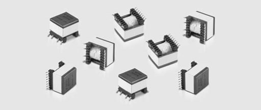
xDSL transformers couple the modem’s analogue front end to a balanced copper line. Their turns ratio, inductance, leakage, winding resistance and linearity must suit the line driver, receiver, termination network and intended DSL profile. A transformer approved for one chipset or band plan is not necessarily interchangeable with another.
DSL increased the data-carrying capability of existing telephone copper infrastructure. The transformer remains part of an analogue line interface: its performance must be evaluated with the protection network, coupling components, splitters where applicable, and the modem’s source and load impedances.
ADSL, HDSL, SHDSL and VDSL
ADSL is asymmetric, allocating different upstream and downstream capacities. Its line interface may coexist with plain old telephone service through the appropriate filtering and frequency separation. ADSL, ADSL2 and ADSL2plus belong to related but distinct recommendations; a single generic data-rate range does not describe every annex or deployment. [4]
HDSL was developed for symmetric digital transmission, including applications associated with T1/E1 services. SHDSL is a related symmetric DSL technology with its own recommendation and requirements. Names such as SDSL and IDSL should not be treated as interchangeable variants of one transformer specification. [4]
VDSL and VDSL2 support higher-bandwidth operation over suitable copper loops, but their attainable rates depend on profile, loop length and line conditions. They are not the latest possible copper-access family: ITU-T G.9701 specifies G.fast. For transformer selection, the useful consequence is that higher-bandwidth interfaces require a line-coupling design explicitly qualified for their intended spectrum and chipset, not an assumed extension of an older ADSL transformer. [4, 5]
Transformer parameters in DSL applications
Table 2 translates the principal DSL transformer parameters into practical selection questions. Numerical limits should come from the modem or line-driver specification and the selected transformer datasheet rather than from a broad DSL-family label.
| Parameter | Why it matters | What to verify |
|---|---|---|
| Magnetising inductance | Loads the line interface at the lower end of the band | Reference winding, tolerance, test level, temperature and bias |
| Leakage inductance | Changes high-frequency transfer and impedance matching | Maximum or tolerance band and shorted-winding measurement connection |
| Winding resistance | Adds attenuation and impedance error | Individual winding resistance and resistance balance |
| Turns ratio | Transforms signal amplitude and impedance | Chipset requirement, winding sections and termination network |
| Capacitance and balance | Affect upper-band response and common-mode conversion | Measurement connection, longitudinal balance and complete interface response |
| Linearity | Limits distortion under the intended excitation | Frequency, drive voltage, termination, temperature and any DC bias |
| Insulation | Separates the external line from equipment circuits | Working voltage, transients, insulation construction and equipment requirements |
Transformer key parameters
Datasheet quantities describe a transformer only when their reference winding and measurement conditions are known. The following discussion concentrates on line transformers, with the power and current-sense differences identified where relevant.
Inductance
Magnetising inductance influences the lower-frequency loading of a signal transformer. Required values vary with chipset impedance, lower band edge, permitted insertion loss, return loss and any intentional filtering function. The inductance must also remain suitable under the actual DC bias and temperature conditions.
Measure open-circuit winding inductance with the other windings open, unless the specification explicitly requires another connection. Record frequency, excitation amplitude, DC bias, temperature and instrument mode. A nominal value measured at low excitation does not establish large-signal linearity or saturation margin.
Leakage inductance
Leakage inductance represents imperfect magnetic coupling. In line interfaces it affects the upper-frequency impedance and transfer response; in hard-switched power converters it also contributes to commutation effects, ringing and switch-voltage overshoot. Some resonant converters deliberately use a specified leakage inductance, so the lowest achievable value is not always the objective. [1]
Specify the reference winding and which windings are shorted during measurement. Use a short, low-inductance connection at the component terminals. The companion article on transformer measurement, leakage inductance and equivalent-circuit modelling explains how these measurements enter a practical model.
DC resistance and longitudinal balance
Winding DC resistance contributes conduction loss and changes the impedance presented to the source and load. In balanced communication interfaces, the symmetry of winding resistance and parasitic elements also matters: imbalance can convert common-mode disturbance into differential interference.
Longitudinal balance describes the interface’s balance with respect to a common reference. Evaluate the complete path, including transformer windings, protection components, terminations, PCB routing and connector arrangement. Low total DCR alone does not guarantee good balance.
Crosstalk
Core geometry and winding placement can reduce magnetic coupling to adjacent channels, but no core shape makes crosstalk irrelevant. Stray fields, capacitive coupling, spacing and PCB routing must be assessed in the assembled interface, particularly where multiple channels share a compact area.
Voltage and safety isolation
Keep dielectric test voltage, continuous working voltage, transient withstand and insulation function distinct. A component can pass a short-duration high-voltage test without being suitable for continuous operation at that voltage. Creepage, clearance, solid insulation, winding-to-core separation and temperature limits remain part of the assessment.
For audio/video, information and communication technology equipment, IEC 62368-1 uses an energy-source and safeguard approach. IEC 62368-1:2023 is the fourth edition; the IEC catalogue identifies a corrected version dated August 2025. Select the edition and national adoption applicable to the target market rather than treating an IEC publication date as a universal regulatory transition date. [6]
Legacy IEC/EN 60950 terminology may still appear in older designs and component documentation. It should not be used as an unqualified current design rule, and a single hipot value must not be presented as complete compliance with either the legacy or current equipment standard.
DC current handling
Determine whether DC actually flows through the relevant winding and whether its ampere-turns are compensated by another winding section. Remote powering, phantom-feed arrangements and current imbalance can create different magnetic conditions. Do not infer a permissible DC current from the DSL family name or from conductor heating alone.
For a biased line transformer, verify inductance, distortion and temperature at the specified operating current. A gap can increase tolerance to uncompensated DC ampere-turns, but also changes inductance and the winding design needed to meet the signal specification.
Turns ratio
The turns ratio sets the ideal voltage transformation and the square-law impedance transformation. The correct ratio depends on the line-driver architecture, desired signal swing, available drive current, receiver connection and termination impedance. Separate transmit, receive or auxiliary winding sections must be connected exactly as specified.
Interwinding capacitance
Interwinding capacitance provides an electric-field coupling path across a galvanic isolation boundary. It can affect signal response and longitudinal balance, and it carries displacement current when the voltage between winding systems changes.
Increasing separation can reduce capacitance but increase leakage. Interleaving often improves magnetic coupling while increasing facing conductor area. In power converters with fast switching edges, evaluate this trade-off against common-mode EMI rather than judging capacitance only from differential signal transfer. [1]
Total harmonic distortion
For the conventional fundamental-referenced definition, total harmonic distortion is the root-sum-square RMS harmonic voltage divided by the RMS fundamental voltage. Let V1 be the fundamental RMS voltage, Vh the RMS voltage of harmonic order h, and H the highest harmonic included. Eq. (1) gives THD as a ratio; multiply by 100 to express it as a percentage.
A total-signal-referenced distortion factor uses a different denominator. State the convention, harmonic bandwidth, test frequency, signal amplitude, source and load impedances, temperature and any DC bias when comparing results.
Core nonlinearity can generate distortion before gross saturation occurs. Low-frequency, high-voltage excitation is particularly demanding because it requires a larger flux excursion for a given turn count. However, higher operating frequency does not by itself guarantee acceptable distortion: use the actual waveform, core material and drive conditions.
Practical design tips for DSL transformers
- Start from the modem or line-driver manufacturer’s transformer specification and reference schematic.
- Verify insertion loss, return loss and longitudinal balance over the complete intended band and with the specified terminations.
- Measure distortion under the highest relevant drive level and any specified bias, including low-frequency operating conditions.
- Include surge protection, splitters and PCB parasitics when checking the complete line interface.
- Confirm insulation construction and equipment-level safety requirements independently of the small-signal performance tests.
Power transformers
Power-transformer selection begins with the converter topology and its winding voltage and current waveforms. Turns ratio, magnetising inductance, reset, volt-second capability, winding loss, core loss and insulation must be evaluated together. A power rating without operating conditions is not sufficient to establish suitability. [1]
Power FLEX transformers
Configurable multiwinding transformers allow standard winding sections to be combined on the PCB. The WE-FLEX example uses six equal-turn windings, permitting several inductance and turns-ratio arrangements. This flexibility does not remove the need to observe winding polarity, current limits, volt-seconds and insulation restrictions. [7]
Loss budgeting in SMPS transformers
Estimate copper and core loss separately, then verify the resulting hot-spot temperatures in the assembled converter. Approximate equality of core and winding loss can be a useful optimisation starting point for some conventional transformer designs, but fixed loss percentages by application are not universal design rules. [1]
| Loss or constraint | Required information | Practical response |
|---|---|---|
| DC-resistance contribution | RMS winding current and resistance at operating temperature | Review conductor area, winding length and connections |
| Additional AC winding loss | Current spectrum, conductor dimensions, layer arrangement and field distribution | Review strand size, foil thickness, interleaving and gap fringing |
| Core loss | Material, flux waveform, frequency, bias and temperature | Review material, core area, turn count and operating flux excursion |
| Leakage-related circuit loss | Leakage inductance, transition current and clamp or resonant behaviour | Distinguish dissipated energy from recovered or intentionally transferred energy |
| Thermal limit | Ambient, airflow, enclosure, PCB mounting and insulation limits | Validate winding and core hot spots in the final assembly |
DC resistance alone underestimates winding loss when skin and proximity effects are significant. Likewise, a sinusoidal core-loss curve must not be applied blindly to a switched waveform. Material data, waveform-aware models and prototype measurements should support the thermal decision. [1]
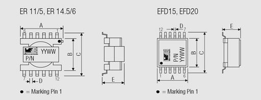
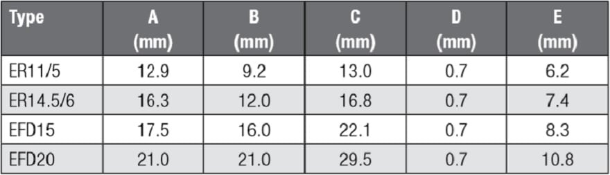
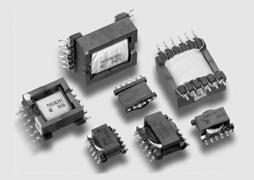
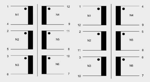
The original mechanical illustrations are useful for understanding package arrangements, but production layout must use the controlled drawing for the exact order code. A shared family name does not establish identical dimensions, electrical ratings or approved insulation construction.
Series and parallel winding connections
PCB connections can create different effective turn counts and turns ratios. Figure 8 retains the original 1:3 connection example. Only equal induced-voltage windings with the correct polarity may be paralleled; an incorrect connection can create a shorted winding or severe circulating current.
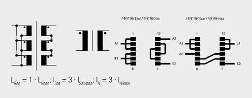
First distinguish uncoupled inductors from windings sharing a core. For two uncoupled inductors with inductances L1 and L2, the equivalent series and parallel inductances are given by Eq. (2).
For equal, tightly coupled winding sections connected series-aiding on the same core, effective turns add and inductance approximately follows the square of the number of sections. For correctly phased parallel sections, effective turns remain unchanged. Let Lbase be the inductance of one section and ns the number connected in series. Eq. (3) gives the idealised relationships.
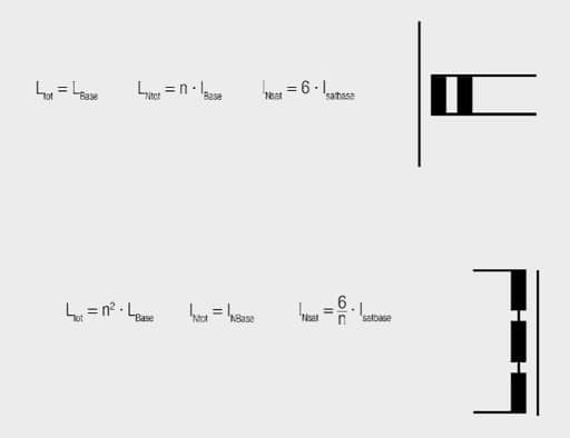
Thus two equal sections in series give approximately 4Lbase, and three give approximately 9Lbase. Parallel sections retain approximately Lbase while reducing effective resistance. Leakage, connection resistance, unequal current sharing and winding tolerances cause departures from the idealised relationships.
Saturation current versus rated winding current
The WE-FLEX definition of Isat,base is important: it is the current in a single winding when all six windings are driven under the stated saturation test. The verified datasheet gives the saturation current per driven winding as six times Isat,base divided by the number of driven windings. This is not the same as the thermal current rating of the conductor. [7]
Let Isat,6∥ denote the total saturation-test current with all six equal sections connected in parallel, and let nI be the number of equally loaded, magnetically additive driven sections. Eq. (4) states the manufacturer-specific relationship.
For three sections in series, the same current flows through every section; the saturation-test terminal current is therefore 2Isat,base. For three sections in parallel, each can carry 2Isat,base under the same magnetic test convention, giving 6Isat,base in total. These magnetic limits do not authorise operation above the winding’s thermal rating. [7]
| Connection | Approximate inductance | Saturation-test terminal current | Ideal thermal-current scaling |
|---|---|---|---|
| One section | Lbase | 6Isat,base | IR,base |
| Two sections in series | 4Lbase | 3Isat,base | IR,base |
| Three sections in series | 9Lbase | 2Isat,base | IR,base |
| Two sections in parallel | Lbase | 6Isat,base total | 2IR,base total |
| Three sections in parallel | Lbase | 6Isat,base total | 3IR,base total |
Table 5 applies to the stated equal-section test convention. It must not be used by adding the magnitudes of primary and secondary load currents in an operating transformer: opposing load ampere-turns largely cancel. Assess the actual excitation, energy-storage interval and net magnetic operating point.
Let IR,base be the rated current of one winding section and np the number of parallel sections. The ideal conductor-current relationships are given by Eq. (5). Parallel scaling assumes adequate current sharing; total heating, AC loss and the final assembly can require further derating.
As a verified example, WE-FLEX 749196221 specifies Lbase = 11.6 µH, IR,base = 0.95 A typical at a 40 K temperature rise, and Isat,base = 0.84 A typical at the stated inductance-change criterion. Three series sections therefore have a calculated magnetic test limit of 1.68 A, but the 0.95 A per-section thermal rating is already lower. The usable current must satisfy the more restrictive application limit. [7]
Volt-seconds, reset and insulation
For forward, bridge and push-pull transformers, winding volt-seconds and reset determine core-flux excursion; conductor current alone is not a saturation criterion. Let vm(t) be the voltage associated with core-linked flux, N the active turn count, Ae the effective core area and ΔB the flux-density change between times t1 and t2. Eq. (6) follows from Faraday’s law. [1]
For periodic steady state, the core flux must return to its starting value over each complete magnetic cycle. Include the reverse-voltage or demagnetisation interval, start-up, current limiting and transient operation. Ending the positive drive pulse does not automatically provide reset. [1]
The verified WE-FLEX datasheet defines a voltage-time rating for one primary section: series sections multiply that rating by their number, while parallel sections retain the single-section rating. The same datasheet specifies a 500 V AC insulation test for 1 s. That short-duration test is not a mains-isolation approval or a continuous working-voltage rating. [7]
PoE power-conversion transformers
A powered Ethernet device contains several distinct functions: PoE detection and classification, input protection and power control, and conversion to the load’s required voltage. An isolated DC-DC stage uses its own power transformer. That transformer does not carry the Ethernet data signal.
PoE-capable LAN magnetics, by contrast, carry the differential data signal while accommodating DC through the appropriate cable-side winding and centre-tap connections. In a balanced phantom-feed arrangement, the DC ampere-turns in the winding halves oppose; imbalance reduces the cancellation. Select those magnetics for the required current, imbalance, temperature and data performance. [2, 3]
IEEE 802.3af, 802.3at and 802.3bt represent successive PoE capabilities. The Ethernet Alliance overview gives maximum PSE output levels of 15.4 W, 30 W, 60 W and 90 W for Types 1, 2, 3 and 4 respectively, with corresponding maximum PD input levels of approximately 13 W, 25.5 W, 51 W and 71.3 W. These figures distinguish power sourced onto the cable from power available at the device interface. [3]
The DC-DC converter’s usable output is lower again because the PD input path and converter dissipate power. Size the power transformer from the converter’s actual input range, output requirements, topology, efficiency target and thermal environment—not directly from the PSE nameplate power.
Flyback conversion is common in suitable PoE power ranges, but it is not the only possible topology. Check magnetising inductance, peak current, RMS winding currents, reset, leakage energy, volt-seconds and output winding arrangements for the selected controller. The PoE interface controller and DC-DC controller may be combined in one IC or implemented separately.
The isolation architecture must satisfy the applicable Ethernet and equipment requirements. Do not infer that every PD must contain an isolated converter in the same location, or that passing one transformer hipot test establishes compliance of the complete power path. Review all electrical connections across the intended barrier, including shields, communication paths and auxiliary supplies. [3, 6]
UNIT and other offline SMPS transformers
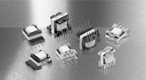
The original UNIT example illustrates transformers intended for mains-fed switched-mode converters. Unlike a mains-frequency transformer connected directly to sinusoidal AC, an offline SMPS transformer is driven by a switching stage supplied from a rectified mains bus. Universal-input capability belongs to the complete converter design, not to the magnetic component alone.
Retain the original illustrative input range of 85 V AC to 265 V AC, but distinguish it from nominal national mains voltages. For sinusoidal input, an ideal bridge and reservoir capacitor charge towards the AC peak. With VAC,rms denoting input RMS voltage and Vbus,peak the ideal no-load capacitor peak, Eq. (7) gives approximately 120 V to 375 V across that range.
Diode drops, capacitor ripple and loading reduce the instantaneous bus below the ideal peak. Surge conditions or an active power-factor-correction stage introduce other voltage limits. Transformer selection must use the actual bus envelope and switching waveform; the original 385 V upper estimate does not follow from 265 V RMS by simple peak conversion.
Low-power offline converters often use flyback-derived operation, including quasi-resonant control. Integrated switching devices can reduce the external component count, but neither integration nor the control label establishes transformer suitability. Check start-up, burst or skip operation, maximum on-time, overload and fault behaviour as well as nominal load.
For mains isolation, define the required insulation function, working voltage, transients, creepage, clearance, solid insulation and temperature class. Verify the exact winding construction and approval scope. A generic product-family illustration is not a construction drawing or safety certificate. [6]
Planar versus conventional winding construction
Planar construction is a winding and packaging choice, not a separate conversion principle. PCB, foil or other flat conductors can provide low profile and repeatable geometry, while conventional wound construction can simplify turn-count changes and early prototyping.
Compare the actual candidates for AC winding loss, interwinding capacitance, leakage, gap fringing, footprint, cooling and insulation. A planar transformer is not inherently lower-loss or lower-capacitance, and operation at a higher switching frequency does not automatically reduce EMI. [1]
CST current-sense transformers
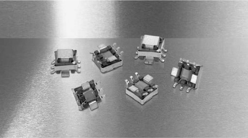
A current-sense transformer reproduces a time-varying primary current as a smaller secondary current, which a burden resistor converts into a voltage. It can provide low insertion loss and galvanic separation, but accurate operation requires adequate magnetising inductance, bandwidth, volt-second margin and reset. An ordinary passive current transformer does not measure steady DC. [8]
In voltage-mode control, the output-voltage error controls the modulator without an inner current-control loop. In current-mode control, an outer voltage loop establishes a current command and an inner loop uses a measured current signal. The exact measured current and control law depend on the converter; the output voltage does not simply become a direct current reference.
A shunt measures current from its resistive voltage drop and can measure DC. A current transformer is useful where low dissipation, isolation or pulse bandwidth makes a shunt less suitable, but it introduces magnetic and reset constraints. Compare the complete measurement chain, not only primary insertion loss. [8]

Turns ratio and burden resistor
Let Np and Ns be primary and secondary turns, and define n = Ns/Np for this section. Let ip be primary current, is the ideal secondary current, RT the burden resistance and uRT the burden voltage. Neglecting excitation current and other errors, Eq. (8) gives the conversion.
Increasing the burden resistance increases sense voltage, but also increases the secondary voltage-time integral and excitation-current error. Include winding resistance and any rectifier drop when calculating the voltage applied to the magnetising branch. Keep the burden and any protective clamp connected as required by the circuit; an unintentionally open secondary can develop excessive voltage.


Magnetising current, pulse droop and reset
Some primary ampere-turns supply the transformer’s excitation rather than the burden current. Referred to the secondary, that excitation current reduces the reproduced signal. During a pulse, magnetising current changes according to the voltage applied to the magnetising inductance. Higher magnetising inductance generally reduces this change, but does not remove the need for reset. [8]
Let Lm,s be secondary-referred magnetising inductance, vs,m(t) the voltage across it and Δim,s its current change during the measurement interval. Eq. (9) gives the linear-inductance approximation.
Unipolar current pulses require an appropriate reverse-voltage interval to restore the magnetic operating point. Inadequate reset can cause progressive saturation and loss of the current signal, compromising regulation or overcurrent protection. High duty ratio, secondary capacitance, rectifier behaviour and the reset clamp can all affect recovery. [8]
Choose the reset network together with the transformer. Check maximum pulse width, available reset time, reset voltage, insulation and controller input protection. Test start-up, overload and the longest permitted pulse rather than relying solely on a nominal switching frequency.
Worked example: 1 A to 5 A at 100 kHz
Retain the original design targets: primary current from 1 A to 5 A, operating frequency 100 kHz, burden voltage 0.1 V at 1 A and 0.5 V at 5 A, and an overall accuracy target of 10%. A primary-to-secondary turns ratio of 1:100 gives n = 100 in Eq. (8).
The ideal secondary current is 10 mA at 1 A primary and 50 mA at 5 A primary. Eq. (10) gives the required burden resistance and confirms the upper-end sense voltage.
At the 1 A minimum input, 10% corresponds to 0.1 A primary-referred error, or 1 mA secondary-referred error. Allocating all of that allowance to magnetising current would leave no budget for burden tolerance, winding resistance, ratio error, rectifier effects, noise or controller error. Use a smaller excitation-current allocation in a complete design.
Two different waveform assumptions illustrate why frequency alone cannot establish the required inductance. For sinusoidal steady state, using RMS quantities and an excitation-current magnitude limit Im,s,max, the inductive-current estimate gives Eq. (11).
The 159 µH result is a sinusoidal excitation-current estimate. It is not automatically the correct minimum for a switched current pulse, and a phasor excitation-current limit is not identical to a complete amplitude-accuracy specification.
For an illustrative flat pulse, additionally assume a maximum on-time of 5 µs, an approximately constant 0.1 V magnetising-branch voltage, and an allowed excitation-current increase of 1 mA during the pulse. This on-time corresponds to a duty ratio of 0.5 at 100 kHz. Eq. (12) gives the pulse-based estimate.
The 500 µH estimate assumes a controlled initial magnetic state and neglects winding voltage drop and other circuit errors. It demonstrates the dependence on pulse width; it is not a completed component selection. Verify the actual current waveform, minimum inductance at temperature, reset circuit and complete error budget. [8]
Key parameters when selecting a current-sense transformer
- Turns ratio and polarity: establish primary-to-secondary current conversion and the required signal direction.
- Burden and winding resistance: determine sense voltage, dissipation and the voltage applied to the magnetising branch.
- Minimum magnetising inductance: limits excitation error and pulse droop under the relevant temperature and test conditions.
- Volt-second capability and reset: prevent loss of magnetic operating margin during the longest pulse and shortest reset interval.
- Leakage and capacitance: influence rise time, ringing, bandwidth and reset behaviour.
- Primary and secondary thermal limits: must accommodate RMS current, repetitive pulses and the actual cooling conditions.
- Insulation: must suit the working voltage, transients and intended separation between the power and measurement circuits.
Design and selection checklist
Translate system requirements into a controlled transformer specification before comparing catalog products or requesting a custom design. Nominal inductance and package similarity are insufficient for either technical interchangeability or purchasing approval.
Define the operating envelope
- Identify the function: signal coupling, power transfer, flyback energy storage, gate drive or current measurement.
- Specify voltage and current waveforms, frequency range, maximum pulse width, duty-ratio limits, bias, imbalance and transient conditions.
- For signal interfaces, state source and load impedances, bandwidth, insertion loss, return loss, balance, distortion and any pulse-response limits.
- For power conversion, state topology, input range, outputs, peak and RMS winding currents, maximum volt-seconds, reset method and cooling conditions.
- For current sensing, state minimum and maximum measured current, burden, accuracy budget, maximum on-time, reset interval and required bandwidth.
Compare datasheet parameters consistently
- Check turns ratio, winding polarity, pinout, centre taps and any integrated chokes or termination components.
- Compare minimum and maximum inductance at matching frequency, amplitude, bias and temperature conditions.
- Confirm the reference winding and shorting arrangement for leakage measurements.
- Separate typical values from guaranteed limits, and magnetic saturation limits from conductor thermal ratings.
- Compare DCR, capacitance, loss and frequency-response data using compatible connections and measurement conventions.
- Validate the simulation model against the intended operating condition; a small-signal model is not automatically a saturation or thermal model.
Choose catalog or custom construction
A catalog transformer is appropriate when its documented electrical, thermal, mechanical and insulation limits fit the application. Custom construction is justified when required ratios, auxiliary windings, parasitic limits, insulation barriers or package constraints cannot be met reliably by a standard part.
For a custom component, control the core material and gap, turn counts, winding order, conductor specification, insulation materials, termination arrangement and acceptance tests. Specify measurable limits for critical parasitics and performance rather than relying on a sample alone.
Qualification, safety and sourcing
- Confirm the required insulation function and distinguish working voltage, dielectric test voltage and transient requirements.
- Check creepage, clearance, solid insulation, winding-to-core separation and temperature limits in the final PCB assembly.
- Verify that any recognition or certification applies to the exact part and construction. Component approval does not replace equipment assessment.
- Measure electrical performance, operating waveforms, temperature rise and EMI over the intended line, load and ambient range.
- For alternate sources, compare test conditions, construction, pinout, parasitic limits and approval scope, not only nominal values.
- Require traceability, controlled drawings and supplier change notification where the design or application demands them.
Conclusion
LAN, xDSL, power-conversion and current-sense transformers share magnetic principles but solve different system problems. Signal interfaces are governed by transfer response, impedance, balance and linearity; power magnetics require topology-specific volt-second, current, loss and thermal analysis; current transformers additionally require a defined burden and reliable reset.
A robust selection uses documented measurement conditions, explicit rating definitions and the actual insulation requirements. Preserve these details when moving from a reference design to a catalog part, custom construction or alternate supplier, then verify performance in the complete circuit.
FAQ
These questions address common engineering and component-selection decisions.
Start with the function: signal coupling, power conversion or current measurement. Then specify the operating waveforms, frequency range, source and load conditions, current, temperature and required insulation. Compare the relevant datasheet limits under matching test conditions. A suitable turns ratio or nominal inductance alone does not establish bandwidth, thermal capability, accuracy or safety suitability.
PoE-capable Ethernet magnetics couple the data signal and accommodate DC through the appropriate cable-side windings and centre taps. The separate power transformer belongs to the DC-DC converter and converts power to the required output. It does not carry Ethernet data. Their bandwidth, current, thermal and insulation requirements must therefore be assessed separately.
Not on inductance alone. The replacement must also match the required turns ratio, winding arrangement, leakage inductance, resistance, capacitance, balance, distortion and insulation. Check the modem or line-driver specification and evaluate the complete interface with its protection and termination components. Matching low-level inductance does not guarantee the required frequency response or large-signal performance.
Equal, tightly coupled winding sections connected series-aiding increase effective turns, so inductance approximately follows the square of the number of sections. Correctly phased parallel sections retain approximately the single-section inductance and can share conductor current. Saturation current follows the magnetic operating conditions and the supplier’s rating definitions, while thermal current remains constrained by conductor loss and cooling.
An ordinary passive current transformer cannot reproduce steady DC. It measures time-varying current and can measure switching pulses when its magnetic operating point is reset appropriately. Selection must include the burden, magnetising inductance, maximum pulse width, reset interval and volt-second capability. For continuous DC measurement, use a measurement method capable of sensing the steady component.
During a measurement pulse, the secondary voltage changes the core flux and magnetising current. The circuit must restore an appropriate magnetic state before the next pulse. Inadequate reset can cause progressive saturation and loss of the measurement signal. Check the longest pulse, available reverse-voltage interval, reset clamp and parasitic capacitance under normal, start-up and fault conditions.
No. A dielectric withstand test applies a specified voltage for a specified duration under defined conditions. It is not automatically a continuous working-voltage rating or complete safety approval. Verify the intended insulation function, working voltage, transients, creepage, clearance, solid insulation and temperature limits, together with the applicable equipment requirements and the exact component construction.
Use a catalog transformer when its documented electrical, thermal, mechanical and insulation limits meet the complete operating envelope. Consider custom construction when standard products cannot provide the required winding ratios, auxiliary outputs, parasitic limits, insulation barriers or package arrangement. Release a controlled construction and test specification, and qualify production samples rather than treating one successful prototype as sufficient evidence.
How to select and validate a transformer
This procedure applies to the electronic transformer families discussed above. Use the relevant interface, converter and equipment requirements for the detailed calculations and acceptance limits.
Select and validate an electronic transformer against its complete application requirements.
- Define the application and operating envelope
Identify signal coupling, power conversion or current measurement. Record voltage and current waveforms, frequency range, pulse width, duty limits, bias, temperature, source and load conditions, and the required insulation function.
- Identify standards and controller requirements
Review the applicable interface and equipment requirements together with the PHY, modem or converter-controller reference design. Separate mandatory limits from typical application values and establish the required measurement conditions.
- Select the transformer family and construction
Choose the appropriate LAN, DSL, power or current-sense family. Compare catalog candidates first, then consider custom construction if winding arrangements, parasitic limits, insulation or mechanical requirements cannot be met by documented standard parts.
- Calculate electrical and magnetic limits
Check turns ratio, inductance, leakage, resistance and capacitance. For power and pulse applications, calculate worst-case volt-seconds and reset. For current sensing, calculate burden voltage, excitation error and pulse droop using the maximum measurement interval.
- Check thermal, mechanical and insulation requirements
Estimate winding and core losses, distinguish saturation current from rated conductor current, and check cooling and hot-spot limits. Verify package tolerances, creepage, clearance, solid insulation and the scope of any component recognition.
- Prototype, qualify and release the specification
Measure the relevant frequency response, operating waveforms, accuracy, temperature rise and EMI over the required operating range. Check start-up and faults. Release the exact part or controlled custom construction with acceptance tests, traceability and change-control requirements.
Further Reading
These articles expand the construction and design-workflow aspects without replacing application-specific calculations or supplier documentation.
- Planar Magnetics: Benefits, Design Practices and When They Make Sense — an overview of planar winding geometry, parasitic trade-offs and thermal integration.
- Conventional versus Planar Switching Power Transformers — a comparison of construction, profile, footprint and manufacturing considerations.
- Planar versus Traditional Transformers in Flyback Converters — application context for comparing winding approaches in isolated converters.
- When to Move from Conventional to Planar Transformers — a worked design-comparison workflow covering electrical, mechanical and production constraints.
References
The numbered references support the application-specific ratings, standards context and design methods cited in the text. Use the exact component revision and applicable standards edition for production design.
- Texas Instruments/Unitrode, Magnetics Design 4: Power Transformer Design, Power Supply Design Seminar, document SLUP126, undated online edition.
- Würth Elektronik, 7490220120: WE-LAN 1000Base-T SMT Transformer with PoE, manufacturer datasheet, revision 004.000, 2024.
- Lennart Yseboodt and David Abramson, Overview of 802.3bt Power over Ethernet, Ethernet Alliance, 2019.
- ITU-T, Series G Recommendations: Transmission Systems and Media, Digital Systems and Networks, ITU, online catalogue, various publication years.
- ITU-T, Recommendation G.9701: Fast Access to Subscriber Terminals, Physical Layer Specification, ITU, 2019, with listed amendments and corrigenda.
- International Electrotechnical Commission, IEC 62368-1:2023: Audio/Video, Information and Communication Technology Equipment, Part 1: Safety Requirements, IEC, fourth edition, 2023; corrected version 2025.
- Würth Elektronik, 749196221: WE-FLEX Flexible Transformer for DC/DC Converter, manufacturer datasheet, revision 004.001, 2025.
- Philip C. Todd, Extend Current Transformer Range, Unitrode Design Note DN-41, Texas Instruments document SLUA174, 1999 online edition.