source: Microwaves & RF articlex
Dec 3, 2015 Jack Browne | Microwaves and RF
Transmission lines vary structurally and performance-wise, and create challenges during the fabrication process when using different active- and passive-circuit components.They establish the pathways for electromagnetic (EM) energy in circuits and systems, in all shapes and sizes. Whether in the form of microstrip structures, such as planar antennas for wireless handheld devices, or the larger waveguide of high-power radar systems, transmission lines of many types transfer high-frequency signals in disparate ways, with or without dielectric substrates. Thus, choose the optimal transmission-line technology for a given application typically depends on the mechanical and electrical design requirements.
Transmission lines based on printed-circuit-board (PCB) materials and semiconductor substrates exhibit a characteristic impedance, typically 50 Ω for high-frequency transmission lines. A transmission line will also behave as a lumped-element structure, with equivalent lumped-element circuit elements: resistance (R), capacitance (C), inductance (L), and transconductance (G).
Such variable parameters make it possible to model the behavior of different transmission lines on a wide range of PCB and semiconductor substrate materials. Those materials play a major role in determining the characteristic impedance of a particular transmission line. Meanwhile material characteristics, such as dielectric constant, dielectric loss, and even the surface roughness of copper conductors, directly impact the performance of circuits fabricated on those materials.
Microstrip
Microstrip is one of the more popular transmission-line types due to its high performance and relative ease of fabrication. It consists of a top conductor layer and bottom ground plane, with a dielectric layer in between (Fig. 1). The characteristic impedance will be determined by the copper weight and quality, the dimensions of the copper-formed circuit traces, and the thickness and qualities of the dielectric material.
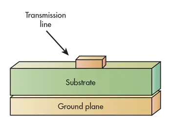
1. Microstrip transmission lines consist of a top conductor layer and bottom ground plane, with a dielectric layer in between.
If anything, microstrip is growing in popularity in concert with the meteoric rise in wireless applications—wireless patch antennas are commonly used in small portable and handheld wireless communications devices. As with other microstrip circuits, microstrip patch antennas are relatively easy to fabricate and can be made with low-profile form factors.
Microstrip-patch-antenna performance usually pinnacles when using thick substrate materials having low dielectric constants, since such materials support good radiation patterns with high efficiency and wide bandwidths. Using thinner PCB substrates with higher dielectric constants will lead to patch antennas with narrower bandwidths and lower efficiency. However, the tradeoff for microstrip circuits fabricated on higher-dielectric-constant PCB materials is reduced circuit dimensions for a given characteristic impedance. Therefore, smaller microstrip circuits (and patch antennas) can be fabricated with PCB materials having higher dielectric constants, although they usually come with higher loss.
Stripline
Stripline is also widely used for RF/microwave PCB designs. In contrast to microstrip, in which EM waves through a conductor propagate through a combination of dielectric material and free space, a conductor in stripline is surrounded on all sides by dielectric material (Fig. 2). The dielectric material in a stripline circuit is sandwiched between top and bottom ground planes. Stripline is somewhat similar in electrical behavior to a coaxial cable, another form of transmission line, in which a center conductor is surrounded by a dielectric material layer that itself is surrounded by a ground-plane layer.
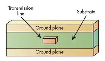
2. Stripline is formed with a conductive strip surrounded on all sides by dielectric material.
One type of conventional stripline circuit is offset stripline, in which the center conductor is not an equal distance from the two ground planes but rather positioned closer to one of the ground planes. Another type is suspended stripline—the conductive layer is mounted on dielectric material but “floats” in a top layer of air, with the ground planes surrounding top and bottom air layers; air contributes its dielectric constant to the mix.
In conventional stripline, the circuit structure’s effective dielectric constant is essentially the same as the relative dielectric constant of the PCB material. For suspended stripline, the effective dielectric constant is a combination of the relative dielectric constant of the PCB material and the dielectric constant of air (about 1).
Suspended stripline is probably the most popular of the different types of stripline. However, fabrication and assembly procedures for forming suspended-stripline circuits can be complex and somewhat expensive versus conventional stripline and microstrip. But suspending the circuit layer in air and surrounding it with a metal housing/ground plane can prove beneficial over conventional stripline in terms of wider bandwidth, improved radiation (less) characteristics, and low circuit losses.
Yet another form of stripline—double-conductor stripline—features two conductors of unequal widths on top of one another, surrounded by dielectric layers that are, in turn, surrounded by ground planes. Double-conductor stripline can be thought of as two microstrip circuits with unequal-width conductor strips laid on top of each other and glued together.
Unfortunately, stripline, suspended stripline, and double-conductor stripline can be difficult to fabricate. Circuit components must be located between the ground planes or additional structures, such as plated viaholes, and machined to make electrical connections to discrete circuit elements and integrated circuits (ICs) that may be surface-mounted on microstrip. Stripline circuit dimensions are considerably narrower for a given characteristic impedance than in microstrip. Therefore, PCB materials for achieving, say, 50-Ω stripline transmission lines will be considerably thicker than for 50-Ω microstrip transmission lines.
Other Transmission-Line Varieties
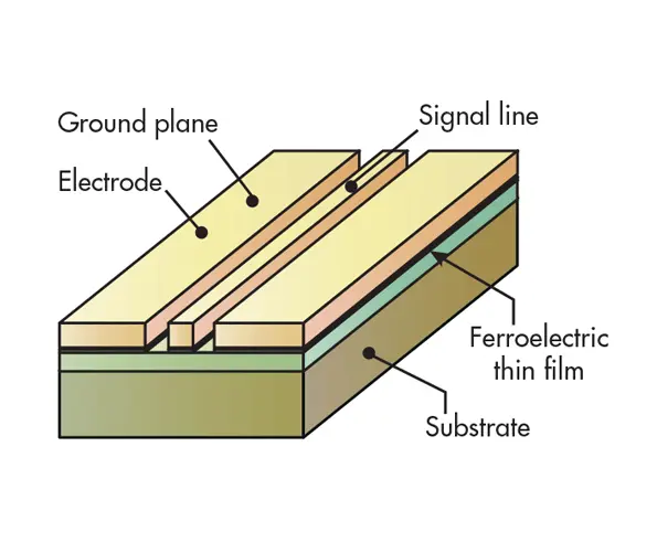
Additional types of transmission lines commonly fabricated on PCB materials for RF/microwave applications include coplanar waveguide (CPW), slotline, finline, and substrate integrated waveguide (SIW).CPW circuit structures consist of a conductor with ground planes on either side, all sitting atop a dielectric material (Fig. 3). In theory, the EM fields propagate through the conductor and the dielectric material with minimal loss. CPW can also be fabricated as grounded coplanar waveguide (GCPW), with an additional ground plane on the bottom of the substrate.
 3. In the creation of CPW transmission lines, a conductor with ground planes on either side sits on top of dielectric material.
CPW is popular for high-frequency circuit design, since discrete circuit elements and active devices can be mounted on top of the circuit, in the manner of microstrip. CPW circuits can support frequencies well into the millimeter-wave frequency region with low loss and, with the dual ground-plane structure, multiple CPW circuits can be connected without discontinuities in the ground plane.
Heat dissipation of CPW circuits depends on the thickness and characteristics of the PCB material. The effective dielectric constant for a CPW substrate is the average of the dielectric material and air since, like microstrip, one-half of the electric field lines are in free space and one-half sit in the dielectric material. CPW circuits offer excellent isolation and support broadband operation, but can require thicker PCB materials to maximize performance.
Slotline consists of a slot between two conductive lines sitting on top of a dielectric substrate. As with microstrip and CPW, the exposed transmission lines make it easy to mount active and passive components. Finline consists of two conductors and ground planes surrounded by PCB dielectric material, with a slot between the two conductors. It generates circular EM fields, and is often applied to the design of circulators and isolators. However, finline is complex and costly to fabricate. SIW transmission lines, which essentially create a rectangular waveguide within a substrate, show great promise for use at millimeter-wave frequencies to 100 GHz and beyond.
Designing circuits with different transmission lines no longer requires the laborious task of working out equations with different dimensions on materials with disparate dielectric constants and other properties. Modern computer-aided-engineering (CAE) tools from leading suppliers, such as ANSYS, AWR Corp., COMSOL, Keysight Technologies, and Sonnet Software provide fast and accurate calculations of transmission-line dimensions for a desired PCB or semiconductor substrate material.
In addition, for the budget-conscious, the MWI-2010 Microwave Impedance Calculator—free software from the Advanced Circuit Materials division of Rogers Corp.—can calculate the key parameters of most RF/microwave transmission lines, including microstrip, stripline, and coplanar-waveguide transmission lines for a selected PCB material. The software runs on Windows-based PCs and can calculate impedance for a set of material parameters, including dielectric constant, thickness, conductor width, and conductor spacing.