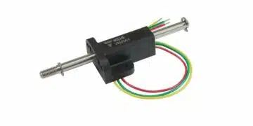


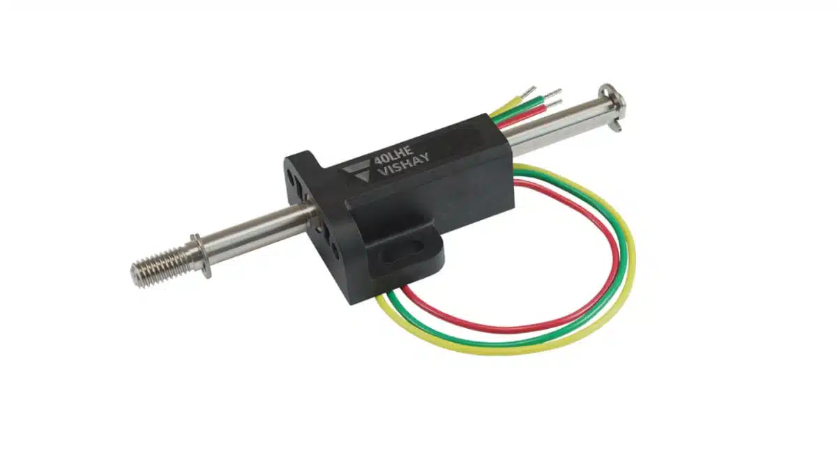
Vishay’s new Sfernice 40 LHE is a compact linear position sensor based on non‑contact Hall Effect technology, designed for accurate displacement measurement up to 40 mm in harsh industrial and mobile environments.
It combines high linearity, fine resolution, and long life with IP67 sealing and integrated electrical protections, making it a practical option for motion control and position feedback where reliability and small form factor are critical.
Key features and benefits
The Vishay 40 LHE is a ready‑to‑use linear position sensor module built around Hall Effect sensing, so there is no mechanical contact between moving and sensing elements. This non‑contact principle typically improves wear performance, stability over time, and resistance to shock and vibration compared to traditional potentiometric position sensors.
Key electrical and mechanical features include:
- Measurement range: displacement measurement up to 40 mm electrical stroke, significantly longer than earlier Vishay devices limited to around 10 mm.
- Linearity: down to ± 1% of full stroke, suitable for many closed‑loop servo and position control applications.
- Resolution: 12 µm, enabling fine motion control and precise small‑signal displacement monitoring.
- Lifespan: greater than 10 million cycles, supporting long‑term use in repetitive actuation or high‑duty‑cycle systems.
- Compact housing: approximately 35 mm × 14.5 mm × 28 mm, making it easy to integrate where sensor real estate is tight.
- Environmental protection: IP67 sealing for resistance to dust and water ingress in outdoor or industrial environments.
- Robustness: withstands high‑frequency vibration up to 20 g and mechanical shocks up to 50 g for demanding applications such as transportation or heavy machinery.
- Supply conditions: operates from a 5 VDC supply with ± 10% tolerance and a typical supply current below 16 mA.
- Output options: available with analog ratiometric output or digital PWM output for flexible interface to controllers and ECUs.
- Load recommendation: designed for use with a recommended load resistance of 1 kΩ on both analog and PWM outputs.
From a design point of view, the integrated reverse polarity and overvoltage protections stand out, as they can remove the need for separate input protection components on the sensor supply line.
Typical applications
The 40 LHE targets motion control and position feedback tasks where strokes are modest in length but accuracy and environmental robustness are important. Typical use cases mentioned by the manufacturer include:
- Structural and infrastructure monitoring:
- Crackmeters for bridges, tunnels, and building structures.
- Displacement monitoring in civil engineering and geotechnical installations.
- Agriculture and digital farming:
- Dendrometers for tree growth measurement.
- Position feedback in agricultural machinery actuators.
- Industrial automation and robotics:
- Robotic grippers and end‑effectors for position or opening width feedback.
- In‑line process displacement measurement in production machinery.
- Medical robotic grasping forceps and similar medical automation systems.
- Electric mobility and transportation:
- Throttle and pedal position sensing in e‑bikes and motorcycles.
- Position feedback in railway equipment and marine applications.
- General machinery:
- Positioning of valves, slides, and small actuators in industrial equipment where IP67 sealing and vibration robustness are needed.
In many of these targets, the sensor will be applied as a feedback element in a servo loop, where the combination of 40 mm stroke, good linearity, and fine resolution helps stabilize control performance.
Technical highlights
This section summarizes the main technical points that are relevant for engineers evaluating the 40 LHE for new designs.
Sensing principle and output behavior
- Non‑contact Hall Effect:
- The sensor detects the magnetic field of a moving element, avoiding wiper contact and associated wear or contact noise.
- The technology supports high cycle life and stable characteristics under vibration.
- Output modes:
- Analog ratiometric output: typically used where the controller has an ADC and expects a proportional voltage over stroke.
- Digital PWM output: suitable for microcontrollers or ECUs that prefer time‑encoded duty cycle signals, potentially offering better noise immunity over longer cable runs.
- True power‑on capability:
- The sensor reports valid position immediately after power‑up.
- No re‑homing, recalibration, or initialization sequence is needed after power interruptions, which simplifies firmware and can remove the need for backup power to retain position.
Electrical robustness
- Reverse voltage protection:
- Can withstand reverse connection down to –10 VDC on the input, helping to protect against wiring mistakes during installation or service.
- Overvoltage protection:
- Tolerates up to +20 VDC on the input, reducing the risk of damage from transients or incorrect supply levels during commissioning.
- Integrated protections:
- By embedding these protections, the module can reduce or eliminate separate TVS diodes, series resistors, or additional protective circuitry on the sensor supply line in many designs.
- This can simplify sensor interface design, reduce BOM count, and save PCB area.
Engineers should still verify the full electrical ratings and transient requirements against the manufacturer datasheet and overall system EMC design.
Mechanical and environmental characteristics
- Sealing: IP67 housing allows temporary immersion and full protection against dust, which suits outdoor equipment, washdown environments, or exposed mechanical assemblies.
- Vibration and shock:
- Rated up to 20 g vibration and 50 g shocks, supporting use in mobile machinery, transportation, and off‑road applications.
- Mounting flexibility:
- “Two faces” fixing holes enable both horizontal and vertical mounting orientations.
- This can simplify mechanical design by allowing the same sensor to be installed in different axes or orientations across platforms.
- Optional spring return:
- A spring return version is available on request for applications such as throttle or pedal position sensing where a defined mechanical return behavior is desirable.
According to Vishay, the device can also be customized to meet specific requirements, which can be relevant for OEMs standardizing a sensor platform across multiple vehicle or machinery variants.
Design‑in notes for engineers
When considering the 40 LHE for a new project, a few practical design‑in aspects are worth highlighting:
- Application envelope and stroke:
- The sensor covers up to 40 mm electrical stroke; check that the intended mechanical movement fits within this range, including tolerances and emergency conditions.
- Make sure mechanical stops and linkages prevent over‑travel that could stress the sensor’s mechanical arrangement.
- Signal interface:
- For analog ratiometric output, match the full‑scale range to your ADC reference, and observe the recommended 1 kΩ load to maintain linearity and accuracy.
- For PWM output, verify that the intended controller can decode the specific PWM frequency and duty‑cycle range defined in the datasheet, and consider filtering where necessary.
- Power supply and protections:
- Although the sensor integrates reverse and overvoltage protections, system‑level EMC and transient suppression may still require additional components (for example, surge protection or filtering).
- Review the 5 VDC rail quality, ripple, and noise against the supply specifications in the official datasheet.
- Mechanical integration:
- Use the dual‑face mounting options to reduce custom bracket complexity, and follow recommended torque values and flatness requirements from Vishay’s mechanical drawings.
- For environments with significant contamination or washdown, ensure cable entry, connectors, and sealing interfaces around the sensor match the IP67 expectations of the overall assembly.
- Safety and diagnostics:
- In safety‑related or mission‑critical systems, consider redundancy, plausibility checks, or secondary sensing channels as required by applicable standards.
- Take advantage of the true power‑on position reporting to simplify fault recovery after power loss; system firmware can resume operation without additional homing cycles, which may improve system availability.
Whenever part selection is safety‑critical or subject to regulatory requirements (for example, in medical, railway, or marine applications), all assumptions should be verified against the latest Vishay datasheet and relevant safety documentation.
Source
This article is based on information provided in the official Vishay Intertechnology press release for the Vishay Sfernice 40 LHE linear position sensor and associated product information, with additional independent commentary for design engineers and component buyers.