


This article explains very basic definition of What is electrical resistance, What is a Resistor ? as passive electronic components and its main application and technologies.
Key Takeaways
- A resistor is a passive electronic component that opposes electric current, converting energy into heat.
- Electrical resistance measures how a material resists the flow of electric charge, with the unit ohm (Ω).
- Ohm’s law defines the relationship between voltage, current, and resistance, helping to calculate power dissipation in resistors.
- Resistors serve many functions in circuits, including current limiting, voltage division, and timing.
- Various resistor types exist, such as fixed and variable, each with specific applications and mounting options.
What Is a Resistor?
A resistor is a passive electronic component that opposes the flow of electric current and converts part of the electrical energy into heat. It is one of the most widely used building blocks in electrical and electronic circuits, from power distribution to microelectronics.
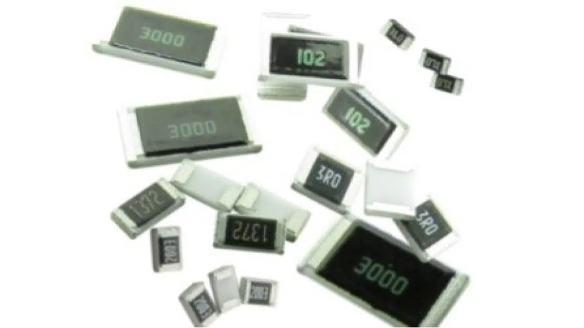
Electrical resistors are widely available in a range of technologies with distinct mountings and packages, and the most common types are fixed resistors. These exhibit an unvarying and pre-defined electrical resistance that cannot be adjusted. The overall impedance is subject to extraneous phenomena like stray capacitance and inductance, which is generally mitigated by the material type used to inhibit the current’s flow, and by the methods of adjustment and of termination.
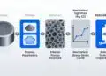
Some of the earliest fixed resistors were based on carbon composition technology. Within the packaging of a carbon composition resistor is a mixture of fine carbon particles and a binding material, like clay. These exhibit broad electrical resistance characteristics with poor tolerance and temperature coefficients of resistance, but prove reliable current regulation and excellent withstanding of pulses and energy surges.
Carbon composition electrical resistors have largely been replaced by devices manufactured through film deposition. These utilize a central ceramic core that has been coated by a functional material like carbon, tantalum nitride (TaN), or a metallic alloy like nichrome (NiCr). The surface mount area is dominated by thick-film chip resistors. These devices are among the cheapest electrical resistors, and also allow designers to attain the highest electrical resistances.
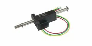
Wirewound electrical resistors are alternatives to carbon composition and film type devices. They are constructed by winding a wire around an insulating core. These are broadly utilized in line input circuits and as fuses due to their surge tolerant failsafe properties. They can generally withstand higher current surges than other resistor types and are well suited to high power applications.
Basic Concept of Electrical Resistance
Electrical resistance expresses how strongly a material or component opposes the flow of electric charge when a voltage is applied. Conductive paths with high resistance pass less current for a given voltage, and dissipate more heat per unit current than low‑resistance paths.
The unit of resistance is the ohm (Ω), defined so that a component has a resistance of 1 Ω if a current of 1 A flows when 1 V is applied across its terminals. Real resistive elements become non‑ideal in extreme conditions such as high frequency (skin effect, dielectric relaxation), very high electric field strength (flashover in highly resistive materials), or very low temperature (superconductivity).
Definition of an Electrical Resistor
An electrical resistor is a passive two‑terminal component designed to provide a specified resistance in a circuit under defined electrical and environmental conditions. In practical usage, resistors are intended to behave with negligible phase shift between applied voltage and resulting current over their rated operating range.
Formally, a resistor is often described as a component R that has no significant distortion of phase at an applied voltage U and the resulting current I. While this ideal definition assumes purely resistive behavior, actual products always exhibit parasitic inductance, capacitance, noise, and non‑linearities that must be accounted for in demanding applications.
Ohm’s Law and Power in Resistors
For an ideal resistor, Ohm’s law defines the relationship between voltage, current, and resistance aswhere U is the voltage across the resistor, I is the current through it, and R is its resistance.
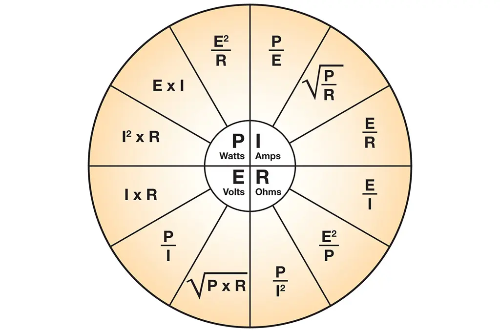
From Ohm’s law, the power dissipated by a resistor can be expressed asThese forms are used in design to verify that the resistor’s power rating will not be exceeded under worst‑case operating conditions. The linear Ohmic relationship is widely used but becomes limited at high frequencies, high field strengths, and in regimes such as superconductivity, where the resistance effectively vanishes.
Key Resistor Parameters (R, P, V, Tolerance, TCR)
Many datasheet parameters describe how a real resistor behaves in its intended environment. The table below summarizes key quantities commonly used in circuit design.
Core electrical and mechanical ratings
| Parameter | Meaning | Typical Design Use |
|---|---|---|
| Nominal resistance (R) | Designed resistance value, usually indicated by color code, printing, or code on the body. | Sets current, voltage division, biasing, time constants. |
| Power rating (P) | Maximum continuous power at rated ambient or terminal temperature. | Ensures safe dissipation without overheating under worst‑case load. |
| Rated temperature | Maximum ambient temperature at which the full power rating may be applied continuously. | Used to derate power capability in hotter environments. |
| Rated terminal part temperature | Maximum allowed temperature at the terminations for SMD parts at full rated power. | Relevant for thermal design on PCBs and for hot‑spot assessments. |
| Derating curve | Relation between ambient or terminal temperature and allowable power, usually in percent. | Defines how much power must be reduced above a defined reference temperature. |
Voltage‑related ratings
| Parameter | Meaning | Typical Design Use |
|---|---|---|
| Rated voltage | Maximum DC or RMS AC voltage that may be applied continuously at rated temperature, derived from rated power and resistance. | Limits operating voltage for a given resistance and power rating. |
| Critical resistance | Highest resistance at which rated power can be applied without exceeding maximum working voltage. | Separates power‑limited and voltage‑limited regions of the resistor’s operating area. |
| Maximum working voltage | Maximum DC or RMS AC voltage that can be continuously applied to the resistor terminations. | Used to ensure creepage/clearance and film thickness are adequate for the application. |
| Overload voltage | Voltage applied for a short time overload test (typically 5 s), usually 2.5× rated voltage or a specified maximum. | Evaluates robustness against transient over‑voltages. |
Accuracy and temperature behavior
| Parameter | Meaning | Typical Design Use |
|---|---|---|
| Tolerance | Allowed deviation of actual resistance from nominal value at reference conditions (for example ±1%, ±5%). | Determines precision of voltage division, bias points, and gain settings. |
| Temperature coefficient (TCR) | Relative change of resistance per kelvin temperature change between two specified temperatures. | Used to estimate drift of resistance over operating temperature range and select technology accordingly. |
Resistor performance is further characterized by parameters such as noise, stability under load, moisture resistance, mechanical robustness, and dielectric withstanding voltage between terminals and outer coating.
Typical Functions of Resistors in Circuits
Resistors appear in almost every electrical and electronic design and serve a wide range of functions.
- Limiting current: Protecting semiconductors and other components by restricting current to safe levels.
- Voltage division: Forming divider networks to generate reference voltages, sense points, or feedback signals.
- Heat generation: Converting electrical energy into heat in braking resistors, load banks, and heaters.
- Matching and loading: Providing defined impedances to match transmission lines or load stages.
- Gain and bias control: Setting amplifier gain, bias currents, and operating points in analog circuits.
- Time constant setting: Combining with capacitors or inductors to define time constants in filters, delays, and snubbers.
- Current measurement: Acting as shunt resistors where the voltage drop is measured to infer current.
Commercial resistor values cover more than nine orders of magnitude, enabling components that are smaller than one square millimeter for electronics, as well as large assemblies for high‑power braking of trains and industrial drives.
Common Resistor Categories (Fixed, Variable, SMD, Through‑Hole)
Resistors can be categorized by their electrical function (fixed vs variable) and by their mechanical form factor (through‑hole vs surface‑mount). These classifications are often combined in practical selection.
Functional categories
- Fixed resistors: Provide a single nominal resistance value that does not change during normal operation.
- Variable resistors: Components such as potentiometers and trimmers that allow manual or mechanical adjustment of the resistance value.
- Special function resistors: Devices like thermistors and shunt resistors that exhibit specific behaviors or are optimized for sensing.
Mounting and packaging categories
| Category | Description | Typical Use |
|---|---|---|
| Through‑hole | Leads inserted into PCB holes and soldered; body often axial or radial. | Power applications, mechanical robustness, easy manual assembly and replacement. |
| SMD (chip) | Leadless rectangular chips soldered to PCB pads. | High‑volume automated assembly, compact layouts, good high‑frequency performance. |
| Networks/arrays | Multiple resistors in a single package, often with common terminals or matched values. | Digital pull‑ups/downs, matched analog networks, space‑efficient high‑density designs. |
Different construction technologies (for example thick film, thin film, wirewound, metal foil) are then used within these categories to optimize resistance range, TCR, noise, pulse handling, and cost.
Example Resistor Applications
The following examples illustrate how resistor parameters and functions come together in real circuits.
- LED current limiter: A fixed SMD resistor in series with an LED restricts forward current based on the supply voltage and LED forward voltage; the selected resistor must satisfy both resistance and power rating requirements.
- Voltage divider for ADC input: Two precision resistors form a divider to scale a higher system voltage down to the input range of an analog‑to‑digital converter, with tolerance and TCR chosen to maintain measurement accuracy over temperature.
- Shunt current sense resistor: A low‑ohmic resistor with tight tolerance and low TCR is placed in series with a load; the voltage across it is measured to determine current, often in power supplies or motor drives.
- Snubber and damping: Resistors combined with capacitors or inductors form snubber networks or damping elements to control transients and ringing in power conversion circuits.
- Braking resistor: A high‑power resistor bank dissipates kinetic energy as heat during regenerative braking of industrial drives or rail vehicles, requiring high overload capability and adequate cooling.
Further Reading on Resistor Types and Selection
For a deeper dive into specific resistor technologies, manufacturing processes, and selection criteria, the following resources provide detailed guidance:
- Resistor Types, Construction and Features – overview of available resistor technologies and how to choose between them for different applications.
- Shunt Current Sense Resistor – focused discussion of low‑ohmic resistors for current measurement.
- Thermistors Basics, NTC and PTC Thermistors – introduction to temperature‑dependent resistors and their typical uses.
These materials extend the basic concepts presented here into practical design workflows, helping engineers select appropriate resistor types and parameters for real‑world circuits.
Conclusion
Resistors are fundamental passive components that form the backbone of electrical and electronic circuit design across virtually every application domain. Understanding their basic operation—governed by Ohm’s law and the conversion of electrical energy into heat—enables engineers to control current, divide voltages, set bias points, define time constants, and measure currents with precision.
The wide range of available resistor technologies, from thick‑film chip resistors for consumer electronics to high‑power wirewound units for industrial braking systems, reflects the diversity of design requirements in modern engineering. Key selection criteria include not only nominal resistance and power rating, but also tolerance, temperature coefficient, voltage rating, and mechanical form factor, all of which must be matched to the specific operating environment and performance targets of each application.
By mastering the fundamental concepts presented in this article—electrical resistance, Ohm’s law relationships, core parameters such as power dissipation and TCR, and the functional roles resistors play in circuits—designers gain the foundation needed to select, specify, and apply resistors effectively. The linked resources on specific resistor types and technologies provide the next step toward deeper expertise in this essential component category.
I’ve created two SEO-optimized schema blocks based on your article “What is a Resistor?” – a Yoast FAQ block and a Yoast How-to block. These are formatted with H3 for main titles and H5 for subtitles, ready to copy-paste directly into your WordPress Gutenberg editor.
FAQ About Resistors
A resistor is a passive electronic component that opposes the flow of electric current and converts electrical energy into heat. It is a fundamental building block used in virtually all electrical and electronic circuits, from power distribution systems to microelectronics, serving functions such as current limiting, voltage division, and timing control.
Electrical resistance is a measure of how strongly a material or component opposes the flow of electric charge when voltage is applied. The unit of resistance is the ohm (Ω), defined such that a component has 1 Ω of resistance if a current of 1 ampere flows when 1 volt is applied across its terminals.
Ohm’s law defines the fundamental relationship between voltage (U), current (I), and resistance (R) as U = I × R. For resistors, this law enables calculation of power dissipation using the formulas P = U × I = I² × R = U²/R. These relationships are essential for ensuring resistor power ratings are not exceeded in circuit design.
Key resistor parameters include nominal resistance value (R), power rating (P), tolerance (acceptable deviation from nominal value), temperature coefficient (TCR – resistance change with temperature), rated voltage, maximum working voltage, and mechanical form factor (through-hole vs surface-mount). All parameters must match the specific operating environment and performance requirements.
Resistors are categorized functionally as fixed resistors (single nominal value), variable resistors (potentiometers and trimmers), and special function resistors (thermistors, shunt resistors). By packaging, they include through-hole resistors (leads inserted into PCB holes), SMD/chip resistors (surface-mount for automated assembly), and resistor networks/arrays (multiple resistors in one package).
Resistors serve multiple critical functions: limiting current to protect semiconductors, forming voltage dividers for reference signals, generating heat in braking systems, matching impedances in transmission lines, controlling amplifier gain and bias, setting time constants in RC/RL circuits, and measuring current via voltage drop (shunt resistors).
The power rating indicates maximum continuous power dissipation at rated ambient temperature. Resistors must be derated (power reduced) at higher temperatures according to manufacturer derating curves. Power is calculated as P = I²R or P = U²/R, and the selected resistor must safely handle worst-case conditions without exceeding its thermal limits.
Through-hole resistors have leads inserted into PCB holes and soldered, offering mechanical robustness and easy manual assembly, ideal for power applications. SMD (surface-mount device) resistors are leadless chips soldered to pads, enabling high-volume automated assembly, compact layouts, and superior high-frequency performance.
How to Select the Right Resistor
- Step 1: Determine the required resistance value
Calculate the nominal resistance needed using Ohm’s law (R = U/I) based on your circuit’s voltage and desired current. Consider the resistor’s function: current limiting, voltage division, pull-up/pull-down, or timing applications. The resistance value sets fundamental circuit behavior such as current flow, voltage levels, and time constants.
- Step 2: Calculate the power dissipation
Determine power dissipation using P = I²R, P = UI, or P = U²/R depending on known parameters. Always apply a safety margin (typically 50-100%) above calculated power to account for transients and tolerances. Select a resistor with a power rating that exceeds your calculated worst-case dissipation.
- Step 3: Check voltage rating requirements
Verify that the circuit voltage does not exceed the resistor’s maximum working voltage. For high-resistance values, voltage limitations may dominate over power limitations. Consider critical resistance (the resistance value where power and voltage limits intersect) and ensure adequate creepage/clearance for your application.
- Step 4: Specify tolerance requirements
Choose tolerance based on precision needs: ±5% for general applications, ±1% for precision circuits, or tighter tolerances (±0.1%, ±0.5%) for measurement and reference applications. Tolerance affects voltage division accuracy, bias point stability, and gain precision in analog circuits.
- Step 5: Evaluate temperature coefficient (TCR)
Select appropriate TCR based on operating temperature range and drift requirements. Typical values range from ±100 ppm/K for general applications to ±5 ppm/K for precision designs. Low TCR is critical for measurement circuits, references, and applications with wide temperature variations.
- Step 6: Choose the form factor and mounting type
Decide between through-hole (for power applications, prototyping, easy replacement) or SMD (for automated assembly, high-density layouts, high-frequency circuits). Consider package size based on available PCB space and thermal dissipation requirements. Resistor networks may save space for multiple identical resistor values.
- Step 7: Select the construction technology
Match technology to requirements: thick-film for cost-effective general use, thin-film for precision and low noise, wirewound for high power and low resistance, metal foil for ultra-precision, or carbon composition for pulse handling. Each technology offers different trade-offs in accuracy, stability, cost, and performance.
- Step 8: Verify additional specifications
Check secondary parameters including noise characteristics (critical for low-signal applications), stability under load, moisture resistance rating, mechanical robustness, pulse handling capability, and dielectric withstanding voltage. Ensure all specifications meet your environmental and reliability requirements.