


This article describes dielectric constant and dissipation factor DF of plastic polymer materials, how to calculate it and factors affecting it.
Key Takeaways
- The article explains the Organic Material Dielectric Constant, emphasizing its role in storing electrical energy in insulating materials.
- Dielectric constant characterizes the ability of materials to store charge and varies among plastics, with common values listed for various materials.
- Dissipation factor (DF) measures energy loss in dielectrics, impacting their efficiency in applications like capacitors and insulation.
- Factors influencing dielectric constant include frequency, moisture, temperature, polymer structure, and voltage.
- Practical applications of these properties are crucial in PCB design, energy storage, and electrical equipment.
What is Dielectric Constant?
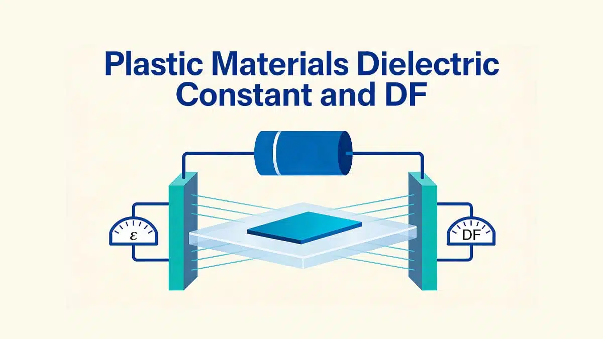
The dielectric constant (Dk) of a plastic or dielectric or insulating material can be defined as the ratio of the charge stored in an insulating material placed between two metallic plates to the charge that can be stored when the insulating material is replaced by vacuum or air. It is also called as electric permittivity or simply permittivity.
And, at times referred as relative permittivity, because it is measured relatively from the permittivity of free space (ε0).
Dielectric constant characterizes the ability of the material to store electrical energy.
Typical values of ε for some referenced and organic dielectrics are:
| Material | Dielectric Constant (ε) |
| Vacuum | 1.000 |
| Dry Air | 1.0059 |
| Foam Polyethylene | 1.6 |
| Fluoropolymers | 2.0 |
| Polypropylene | 2.1 |
| Butyl Rubber | 2.3 |
| SBR | 2.9 |
| Silicone Rubber | 3.2 |
| Plexiglass | 3.4 |
| PVC | 4.0 |
| Glass | 3.8-14.5 |
| Distilled Water | ~80 |
A dielectric constant of 2 means an insulator will absorb twice more electrical charge than vacuum.
Applications include:
Use of materials in the production of capacitors used in radios and other electrical equipment. Commonly used by circuit designers to compare different printed-circuit-board (PCB) materials.
Development of materials for energy storage applications.
For example, polymer-based dielectric composites are highly desirable for applications ranging from electronic packaging, embedded capacitors, to energy storage. These composites are highly flexible with a low process temperature and they exhibit a relatively high dielectric constant, low dielectric loss, high dielectric strength.
How to Calculate Dielectric Constant?
In other words, dielectric constant can also be defined as the ratio of the capacitance induced by two metallic plates with an insulator between them, to the capacitance of the same plates with air or a vacuum between them.
An insulating material with higher dielectric constant is needed when it is to be used in E&E applications where high capacitance is needed.
If a material were to be used for strictly insulating purposes, it would be better to have a lower dielectric constant.
The dielectric constant formula is:
Where:
- C = capacitance using the material as the dielectric capacitor
- C0 = capacitance using vacuum as the dielectric
- ε0 = Permittivity of free space (8.85 x 10⁻¹² F/m i.e. Farad per metre)
- A = Area of the plate/sample cross section area
- T = Thickness of the sample
Dielectric Constant Units: This electrical property is a dimensionless measure.
The most generally used standard tests to calculate dielectric constant for plastics are ASTM D2520, ASTM D150 or IEC 60250 (ofcourse there exist several other methods as well, but they are not discussed here).
The method includes:
A sample is placed between two metallic plates and capacitance is measured. A second run is measured without the specimen between the two electrodes. The ratio of these two values is the dielectric constant. The test can be conducted at different frequencies, often between the 10Hz and 2MHz range
- The sample must be flat and larger than the 50mm (2 in) circular electrodes used for the measurement.
Example: Calculating dielectric constant of a PP plaque
Consider a flat polypropylene sample with area A = 50 mm × 50 mm and thickness T = 1.0 mm placed between 50 mm circular electrodes at 1 kHz. The measured capacitance with the sample is C = 47 pF, and the capacitance without sample (air) is C₀ = 21 pF. The relative permittivity is then ε = C / C₀ ≈ 47 / 21 ≈ 2.24, which is consistent with typical PP values reported in the table (around 2.3).
passive-components
Polar Plastics Vs Non-polar Plastics
Dielectric properties of a polymer largely depend upon their structure. The structure determines whether a polymer is polar or non-polar and this in turn decided the electrical properties of the polymer.
- In polar polymers (PMMA, PVC, Nylon, PC etc.), dipoles are created due to imbalance in the distribution of electrons. These dipoles tend to align in the presence of electric field. Hence, this creates dipole polarization of the material making these materials only moderately good as insulators.
- While non-polar polymers (PTFE, PP, PE, PS) have symmetrical molecules and are truly covalent. There are no polar dipoles present in them and hence in presence of electric field does not align the dipoles. However, slight electron polarization occurs due to the movement of electrons in the direction of electric field, which is effectively instantaneous. These polymers have high resistivities and low dielectric constant.
Polar plastics have a tendency to absorb moisture from the atmosphere. Presence of moisture raises the dielectric constant and lowers the resistivity. With rise in temperature, there is faster movement of polymer chains and fast alignment of dipoles. This invariably raises the dielectric constant values for polar plastics.
Non-polar plastics are not affected by moisture and rise in temperature.
Factors Influencing Dielectric Constant
- Frequency – Dielectric constant decreases abruptly as frequency increases
- Moisture &Temperature
- Voltage
- Structure & morphology (see polar plastics vs non-polar plastics)
- Presence of other materials in the plastic
- Weathering and Deterioration
DF Dissipation Factor
Dissipation factor (DF or tan δ) is the electrical property of plastics and other electrical insulating materials. It is defined as the ratio of the insulating material’s equivalent series resistance ESR (Equivalent Series Resistance or ESR) to its capacitive reactance at a specified frequency.
In other words, it is defined as a ratio between the permittivity and the conductivity of an electrical insulating material. The property is also referred as the tangent of the loss angle, loss tangent, tan delta, approx. power factor… It measures the electrical energy absorbed and lost (power dissipation) when electrical current is applied to an insulating material. Most of the absorbed energy is dissipated as heat.
Dielectric Constant and Dissipation Factor in Design
In practical component and PCB design, dielectric constant and dissipation factor have to be considered together. High‑k polymers such as PVDF‑based materials provide increased capacitance density but often come with significantly higher DF, which limits their use at high frequency or high ripple current. Low‑k, low‑DF materials such as PTFE or PP are preferred in RF, microwave and high‑Q resonant applications, where dielectric losses directly translate into insertion loss or reduced efficiency. The combined ε / DF table below allows quick screening of candidate polymers for a given capacitance and loss budget.
Plastics and Importance of DF
Dissipation factor indicates the inefficiency of material to hold energy or behave as an insulating material. The lower the dissipation factor, the more efficient is the insulator system. Most plastics have relatively lower dissipation factor at room temperature. Dissipation Factor is a dimensionless measure and hence no units.
In parallel with dissipation factor, designers always look at the dielectric constant (relative permittivity) of the polymer. Dielectric constant controls capacitance density and signal propagation velocity, while DF controls dielectric losses and heating. High‑k, high‑DF materials can be attractive for energy storage at low frequency, whereas low‑k, ultra‑low‑DF materials dominate RF and high‑speed interconnect applications.
Example: Relating DF to ESR in a film capacitor
A plastic film capacitor has capacitance C = 100 nF and ESR = 0.5 Ω at 100 kHz. The reactance is Xc = 1 / (2π f C) ≈ 15.9 Ω, so DF = ESR / Xc ≈ 0.5 / 15.9 ≈ 0.031 (3.1%). If the same dielectric formulation is optimized and ESR drops to 0.1 Ω, DF reduces to about 0.6%, which directly cuts dielectric heating in the application.
In an ideal capacitor, current leads voltage by 90°, so the phase angle is purely reactive and DF is zero. Real plastic dielectrics always exhibit some resistive component in parallel or in series with the capacitance, which shifts the phase angle and creates a finite loss angle whose tangent is the dissipation factor. This behaviour is often modelled as an ideal capacitor in series with an ESR, making DF directly proportional to ESR at a given frequency.
passive-components
Dielectric Constant (ε) and DF Values of Several Plastics
| Polymer Type | ε Min | ε Max | DF Min | DF Max |
|---|---|---|---|---|
| ABS – Acrylonitrile Butadiene Styrene | 2.70 | 3.20 | 50 | 190 |
| ABS Flame Retardant | 2.80 | 3.00 | 70 | 90 |
| ABS High Heat | 2.40 | 5.00 | 20 | 350 |
| ABS High Impact | 2.40 | 5.00 | 20 | 350 |
| ABS/PC Blend – Acrylonitrile Butadiene Styrene/Polycarbonate Blend | 2.90 | 3.20 | 70 | 200 |
| ABS/PC Blend 20% Glass Fiber | 3.10 | 3.20 | 20 | 90 |
| Amorphous TPI Blend, Ultra-high heat, Chemical Resistant (Standard Flow) | 3.50 | 3.50 | 0.001 | 0.001 |
| ASA – Acrylonitrile Styrene Acrylate | 3.30 | 3.80 | 90 | 340 |
| ASA/PC Blend – Acrylonitrile Styrene Acrylate/Polycarbonate Blend | 3.00 | 3.40 | 20 | 190 |
| ASA/PC Flame Retardant | 3.20 | 3.20 | 110 | 170 |
| CA – Cellulose Acetate | 3.00 | 8.00 | 100 | 1000 |
| CAB – Cellulose Acetate Butyrate | 3.00 | 7.00 | 100 | 400 |
| CP – Cellulose Proprionate | 3.00 | 4.00 | 60 | 300 |
| CPVC – Chlorinated Polyvinyl Chloride | 3.00 | 6.00 | 100 | 200 |
| ECTFE | 2.57 | 2.59 | 130 | 170 |
| ETFE – Ethylene Tetrafluoroethylene | 2.60 | 2.60 | 6 | 100 |
| EVA – Ethylene Vinyl Acetate | 2.50 | 3.00 | 130 | 1000 |
| EVOH – Ethylene Vinyl Alcohol | 4.80 | 5.60 | 1800 | 2200 |
| FEP – Fluorinated Ethylene Propylene | 2.10 | 2.10 | 7 | 7 |
| HDPE – High Density Polyethylene | 2.30 | 2.30 | 3 | 20 |
| HIPS – High Impact Polystyrene | 2.40 | 4.80 | 4 | 20 |
| HIPS Flame Retardant V0 | 2.00 | 3.00 | 5 | 50 |
| LCP – Liquid Crystal Polymer | 3.30 | 3.30 | 20 | 20 |
| LCP Glass Fiber-reinforced | 3.00 | 4.00 | 40 | 40 |
| LCP Mineral-filled | 3.00 | 5.90 | 60 | 300 |
| LDPE – Low Density Polyethylene | 2.30 | 2.30 | 70 | 280 |
| LLDPE – Linear Low Density Polyethylene | 2.30 | 2.30 | 3 | 4 |
| MABS – Transparent Acrylonitrile Butadiene Styrene | 2.80 | 3.00 | 2.8 | 3 |
| PA 11 – (Polyamide 11) 30% Glass fiber reinforced | 4.80 | 4.80 | 0.03 | 0.03 |
| PA 11, Conductive | 3.00 | 9.00 | 0.05 | 0.25 |
| PA 11, Flexible | 3.00 | 9.00 | 0.05 | 0.25 |
| PA 11, Rigid | 3.00 | 9.00 | 0.05 | 0.25 |
| PA 12 (Polyamide 12), Conductive | 3.00 | 9.00 | 0.05 | 0.25 |
| PA 12, Fiber-reinforced | 3.00 | 9.00 | 0.05 | 0.25 |
| PA 12, Flexible | 3.00 | 9.00 | 0.05 | 0.25 |
| PA 12, Glass Filled | 3.00 | 9.00 | 0.05 | 0.25 |
| PA 12, Rigid | 3.00 | 9.00 | 0.05 | 0.25 |
| PA 46 – Polyamide 46 | 3.40 | 3.80 | 190 | 600 |
| PA 46, 30% Glass Fiber | 4.00 | 4.60 | 23 | 90 |
| PA 6 – Polyamide 6 | 4.00 | 5.00 | 100 | 600 |
| PA 6-10 – Polyamide 6-10 | 3.00 | 4.00 | 400 | 400 |
| PA 66 – Polyamide 6-6 | 4.00 | 5.00 | 100 | 400 |
| PA 66, 30% Glass Fiber | 3.50 | 5.60 | 100 | 1500 |
| PA 66, 30% Mineral filled | 4.00 | 5.00 | 200 | 1500 |
| PA 66, Impact Modified, 15-30% Glass Fiber | 3.40 | 4.20 | 130 | 200 |
| PA 66, Impact Modified | 2.90 | 5.00 | 100 | 2000 |
| PAI – Polyamide-Imide | 3.90 | 7.30 | 60 | 710 |
| PAI, 30% Glass Fiber | 4.20 | 6.50 | 220 | 500 |
| PAR – Polyarylate | 3.30 | 3.30 | 20 | 200 |
| PBT – Polybutylene Terephthalate | 2.90 | 4.00 | 10 | 200 |
| PBT, 30% Glass Fiber | 3.00 | 4.00 | 20 | 120 |
| PC (Polycarbonate) 20-40% Glass Fiber | 3.00 | 3.50 | 9 | 75 |
| PC (Polycarbonate) 20-40% Glass Fiber Flame Retardant | 3.00 | 3.80 | 9 | 100 |
| PC – Polycarbonate, high heat | 2.80 | 3.80 | 69 | 100 |
| PC/PBT blend, Glass Filled | 3.30 | 3.90 | 100 | 200 |
| PCTFE – Polymonochlorotrifluoroethylene | 2.00 | 3.00 | 10 | 250 |
| PE – Polyethylene 30% Glass Fiber | 2.70 | 2.80 | 20 | 80 |
| PEEK – Polyetheretherketone | 3.20 | 3.20 | 30 | 30 |
| PEEK 30% Carbon Fiber-reinforced | 3.20 | 3.40 | 29 | 32 |
| PEEK 30% Glass Fiber-reinforced | 3.30 | 4.20 | 20 | 20 |
| PEI – Polyetherimide | 3.10 | 3.20 | 13 | 25 |
| PEI, 30% Glass Fiber-reinforced | 3.00 | 4.00 | 15 | 53 |
| PEI, Mineral Filled | 3.00 | 4.00 | 10 | 15 |
| PEKK (Polyetherketoneketone), Low Cristallinity Grade | 3.30 | 3.30 | 0.004 | 0.004 |
| PESU – Polyethersulfone | 3.50 | 4.10 | 10 | 140 |
| PESU 10-30% glass fiber | 4.20 | 4.30 | 70 | 100 |
| PET – Polyethylene Terephtalate | 3.00 | 4.00 | 20 | 200 |
| PET, 30% Glass Fiber-reinforced | 3.00 | 4.00 | 120 | 1680 |
| PETG – Polyethylene Terephtalate Glycol | 3.00 | 4.00 | 20 | 300 |
| PFA – Perfluoroalkoxy | 2.10 | 2.10 | 2 | 2 |
| PI – Polyimide | 3.10 | 3.55 | 18 | 50 |
| PMMA – Polymethylmethacrylate/Acrylic | 2.00 | 5.00 | 200 | 200 |
| PMMA (Acrylic) High Heat | 3.20 | 4.00 | 400 | 600 |
| PMMA (Acrylic) Impact Modified | 2.90 | 3.70 | 300 | 400 |
| PMP – Polymethylpentene | 2.10 | 3.60 | 0.7 | 30 |
| POM – Polyoxymethylene (Acetal) | 3.30 | 4.70 | 50 | 110 |
| POM (Acetal) Impact Modified | 4.00 | 4.30 | 50 | 250 |
| POM (Acetal) Low Friction | 3.00 | 4.00 | 20 | 90 |
| PP – Polypropylene 10-20% Glass Fiber | 2.60 | 2.60 | 10 | 20 |
| PP, 10-40% Mineral Filled | 2.30 | 2.30 | 7 | 11 |
| PP, 10-40% Talc Filled | 2.30 | 2.30 | 7 | 11 |
| PP, 30-40% Glass Fiber-reinforced | 2.60 | 2.60 | 10 | 20 |
| PP (Polypropylene) Copolymer | 2.30 | 2.30 | 3 | 5 |
| PP (Polypropylene) Homopolymer | 2.30 | 2.30 | 3 | 5 |
| PP, Impact Modified | 2.30 | 2.30 | 3 | 5 |
| PPA – Polyphthalamide | 4.30 | 4.30 | 270 | 270 |
| PPA, 33% Glass Fiber-reinforced – High Flow | 3.70 | 3.90 | 0.014 | 0.016 |
| PPA, 45% Glass Fiber-reinforced | 4.40 | 4.60 | 0.9 | 0.2 |
| PPE – Polyphenylene Ether | 2.70 | 2.70 | 4 | 9 |
| PPE, 30% Glass Fiber-reinforced | 2.90 | 2.90 | 10 | 15 |
| PPE, Flame Retardant | 2.70 | 2.70 | 7 | 31 |
| PPS – Polyphenylene Sulfide | 3.00 | 3.30 | 4 | 30 |
| PPS, 20-30% Glass Fiber-reinforced | 3.30 | 3.80 | 10 | 32 |
| PPS, 40% Glass Fiber-reinforced | 4.00 | 4.00 | 13 | 20 |
| PPS, Glass fiber & Mineral-filled | 5.00 | 5.00 | 70 | 580 |
| PPSU – Polyphenylene Sulfone | 3.40 | 3.50 | 17 | 50 |
| PS (Polystyrene) 30% glass fiber | 2.50 | 2.50 | 5 | 28 |
| PS (Polystyrene) Crystal | 2.40 | 2.70 | 1 | 28 |
| PS, High Heat | 2.40 | 2.70 | 1 | 28 |
| PSU – Polysulfone | 3.00 | 3.20 | 8 | 64 |
| PSU, 30% Glass finer-reinforced | 3.60 | 3.70 | 40 | 60 |
| PTFE – Polytetrafluoroethylene | 2.10 | 2.10 | 2 | 2 |
| PTFE, 25% Glass Fiber-reinforced | 3.00 | 3.00 | 5 | 5 |
| PVC, Plasticized | 3.00 | 5.00 | 400 | 1600 |
| PVC, Plasticized Filled | 3.00 | 5.00 | 400 | 1600 |
| PVC Rigid | 3.00 | 4.00 | 60 | 200 |
| PVDF – Polyvinylidene Fluoride | 6.00 | 9.00 | 200 | 1700 |
| SAN – Styrene Acrylonitrile | 2.50 | 3.40 | 70 | 100 |
| SAN, 20% Glass Fiber-reinforced | 3.20 | 3.80 | 10 | 100 |
| SMA – Styrene Maleic Anhydride | 2.80 | 2.80 | 40 | 40 |
| SMMA – Styrene Methyl Methacrylate | 3.20 | 3.20 | 400 | 400 |
Typical Use Cases by Polymer Family (ε and DF)
- PTFE, FEP, PFA: Very low ε and extremely low DF, used in RF/microwave cables, high‑frequency PCB laminates and precision timing capacitors.
- PP, PE, PMP: Low ε and low DF, standard dielectrics for film capacitors, DC‑link capacitors and low‑loss power electronics insulation.
- PPS, PEEK, LCP: Medium ε with relatively low DF, suitable for high‑temperature SMT film capacitors, high‑speed digital substrates and automotive under‑hood electronics.
- PVC, PA, PET, PC: Higher ε and significantly higher DF, mainly used for general‑purpose insulation, wire and cable jacketing, connectors and structural parts where losses are less critical.
- PVDF and blends: High‑k dielectrics for energy‑dense film capacitors, embedded capacitors and actuators, typically limited to lower frequencies because of higher DF.
Find commercial grades matching your electrical property target using “Property Search – Dielectric Constant” filter in Omnexus Plastics Database.
Read more about plastic materials features:
- Omnexus / SpecialChem, “Dielectric Constant – Polymer Properties Database”
- Omnexus / SpecialChem, “Dissipation Factor – Polymer Properties Database”
- Passive Components Blog, “Dielectric, Permittivity, Dipoles and Dielectric Absorption”
- Passive Components Blog, “Capacitors Losses, ESR, Impedance, DF and Q”
- Flammability of Polymer Materials and UL94 Explained
- Coefficient of Linear Thermal Expansion on Polymers Explained
Conclusion
Dielectric constant and dissipation factor together describe how plastic materials store and dissipate electrical energy across frequency, temperature and environmental conditions. Dielectric constant (relative permittivity) sets capacitance density and signal propagation, while dissipation factor quantifies dielectric losses, heating and efficiency limits in real components and insulation systems.
By combining a clear understanding of polymer structure (polar versus non‑polar), moisture and morphology effects with the ε / DF tables and typical use‑case guidelines, designers can quickly shortlist suitable plastics for capacitors, PCB laminates, cables and high‑frequency or high‑voltage insulation applications.
FAQ
The dielectric constant (also called relative permittivity) is the ratio of the capacitance of a material compared to vacuum. It measures the ability of plastics to store electrical energy. Typical values range from 2.0 for PTFE to 9.0 for PVDF, while water is around 80.
It determines how plastics behave in electrical and electronic applications. High dielectric constant materials are used in capacitors and energy storage, while low values are preferred for insulation and PCB substrates.
The dissipation factor (DF) measures energy loss within a dielectric material when exposed to an alternating electric field. A lower DF indicates higher efficiency and better insulation properties.
Key factors include frequency, temperature, moisture absorption, polymer structure (polar vs. non-polar), voltage, and material morphology. Polar plastics like PVC and Nylon show higher sensitivity to moisture and temperature than non-polar plastics like PTFE or PP.
Applications include capacitors, PCB substrates, embedded energy storage, high-frequency circuits, and insulation in automotive and aerospace electronics.
How to Measure Dielectric Constant of Plastic Materials
- Prepare the sample
Cut a flat plastic specimen larger than the 50 mm electrodes used in the test setup.
- Place between electrodes
Insert the sample between two metallic plates connected to a capacitance meter.
- Measure capacitance with sample
Record the capacitance value when the plastic sample is in place.
- Measure capacitance without sample
Remove the sample and measure the capacitance of the air gap (vacuum equivalent).
- Calculate dielectric constant
Use the formula: ε = C / C₀, where C is capacitance with the sample and C₀ is capacitance with air.


