

Passive Components Blog
No Result
View All Result
  • Home
  • News
    • All
    • Aerospace & Defence
    • Antenna
    • Applications
    • Automotive
    • Capacitors
    • Circuit Protection Devices
    • electro-mechanical news
    • Filters
    • Fuses
    • Inductors
    • Industrial
    • Integrated Passives
    • inter-connect news
    • Market & Supply Chain
    • Market Insights
    • Medical
    • Modelling and Simulation
    • New Materials & Supply
    • New Technologies
    • Non-linear Passives
    • Optoelectronics and Isolation
    • Oscillators
    • Passive Sensors News
    • Resistors
    • RF & Microwave
    • Telecommunication
    • Weekly Digest
    Würth Elektronik WE-LHMI and WE-HCI power inductor comparison slide showing current ratings and maximum operating temperatures

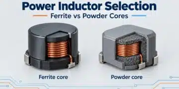
    Power Inductor Selection: Ferrite vs Powder Core Trade-Offs, Würth Elektronik Webinar

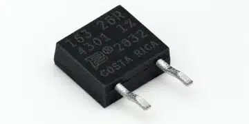
    Bourns PWR163 DPAK-style surface-mount power resistor with moulded housing, metal backplate and terminals

    Bourns Releases Power Resistor Adds Reverse-Pin Configuration

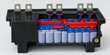
    Conceptual polypropylene DC-link film capacitor module with parallel cells and copper interconnections

    DC-Link Film Capacitor Modules: Inductance and Thermal Design, Jianghai-Europe Tech Memo

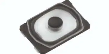
    Panasonic EVP-BX surface-mount tactile switches with top-push actuators and two-terminal construction

    Panasonic EVP-BX Quiet Tactile Switches for HMI Designs

    Motor Run Capacitor Safety Classes S0–S3: A Design Guide

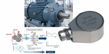
    YAGEO Piezoelectric Sensors for Predictive Maintenance

    Wk 44 Electronics Supply Chain Digest

    TDK HVC28 and HVC29 high-voltage DC contactors with black housings and main power terminals

    TDK Introduces Gas-Filled High-Voltage DC Contactors up to 600 A

    Murata SWL RF coaxial switch connector measurement diagram and SWL-to-SWJ board-area comparison.

    Murata RF Switch Connectors Cut PCB Test-Point Area

    Trending Tags

    • Ripple Current
    • RF
    • Leakage Current
    • Tantalum vs Ceramic
    • Snubber
    • Low ESR
    • Feedthrough
    • Derating
    • Dielectric Constant
    • New Products
    • Market Reports
  • Knowledge Blog
  • Dossiers
    • Aerospace and Defense Passive Components Dossier
    • AI Hardware Dossier
    • Automotive Dossier
    • Industrial Robotics Dossier
    • Power Converter Dossier
    • Capacitor Dossier
    • Circuit Protection Dossier
    • Inductor Dossier
    • Resistor Dossier
    • Silicon Capacitors and Integrated Passives Dossier
  • Suppliers
    • Who is Who
  • PCNS
    • PCNS 2025
    • PCNS 2023
    • PCNS 2021
    • PCNS 2019
    • PCNS 2017
  • Events
  • Home
  • News
    • All
    • Aerospace & Defence
    • Antenna
    • Applications
    • Automotive
    • Capacitors
    • Circuit Protection Devices
    • electro-mechanical news
    • Filters
    • Fuses
    • Inductors
    • Industrial
    • Integrated Passives
    • inter-connect news
    • Market & Supply Chain
    • Market Insights
    • Medical
    • Modelling and Simulation
    • New Materials & Supply
    • New Technologies
    • Non-linear Passives
    • Optoelectronics and Isolation
    • Oscillators
    • Passive Sensors News
    • Resistors
    • RF & Microwave
    • Telecommunication
    • Weekly Digest
    Würth Elektronik WE-LHMI and WE-HCI power inductor comparison slide showing current ratings and maximum operating temperatures

    Power Inductor Selection: Ferrite vs Powder Core Trade-Offs, Würth Elektronik Webinar

    Bourns PWR163 DPAK-style surface-mount power resistor with moulded housing, metal backplate and terminals

    Bourns Releases Power Resistor Adds Reverse-Pin Configuration

    Conceptual polypropylene DC-link film capacitor module with parallel cells and copper interconnections

    DC-Link Film Capacitor Modules: Inductance and Thermal Design, Jianghai-Europe Tech Memo

    Panasonic EVP-BX surface-mount tactile switches with top-push actuators and two-terminal construction

    Panasonic EVP-BX Quiet Tactile Switches for HMI Designs

    Motor Run Capacitor Safety Classes S0–S3: A Design Guide

    YAGEO Piezoelectric Sensors for Predictive Maintenance

    Wk 44 Electronics Supply Chain Digest

    TDK HVC28 and HVC29 high-voltage DC contactors with black housings and main power terminals

    TDK Introduces Gas-Filled High-Voltage DC Contactors up to 600 A

    Murata SWL RF coaxial switch connector measurement diagram and SWL-to-SWJ board-area comparison.

    Murata RF Switch Connectors Cut PCB Test-Point Area

    Trending Tags

    • Ripple Current
    • RF
    • Leakage Current
    • Tantalum vs Ceramic
    • Snubber
    • Low ESR
    • Feedthrough
    • Derating
    • Dielectric Constant
    • New Products
    • Market Reports
  • Knowledge Blog
  • Dossiers
    • Aerospace and Defense Passive Components Dossier
    • AI Hardware Dossier
    • Automotive Dossier
    • Industrial Robotics Dossier
    • Power Converter Dossier
    • Capacitor Dossier
    • Circuit Protection Dossier
    • Inductor Dossier
    • Resistor Dossier
    • Silicon Capacitors and Integrated Passives Dossier
  • Suppliers
    • Who is Who
  • PCNS
    • PCNS 2025
    • PCNS 2023
    • PCNS 2021
    • PCNS 2019
    • PCNS 2017
  • Events
No Result
View All Result
Passive Components Blog
No Result
View All Result

What is the Difference Between X8G, X8L and X8R Ceramic Capacitor Dielectrics?

25.8.2026
Reading Time: 4 mins read
A A

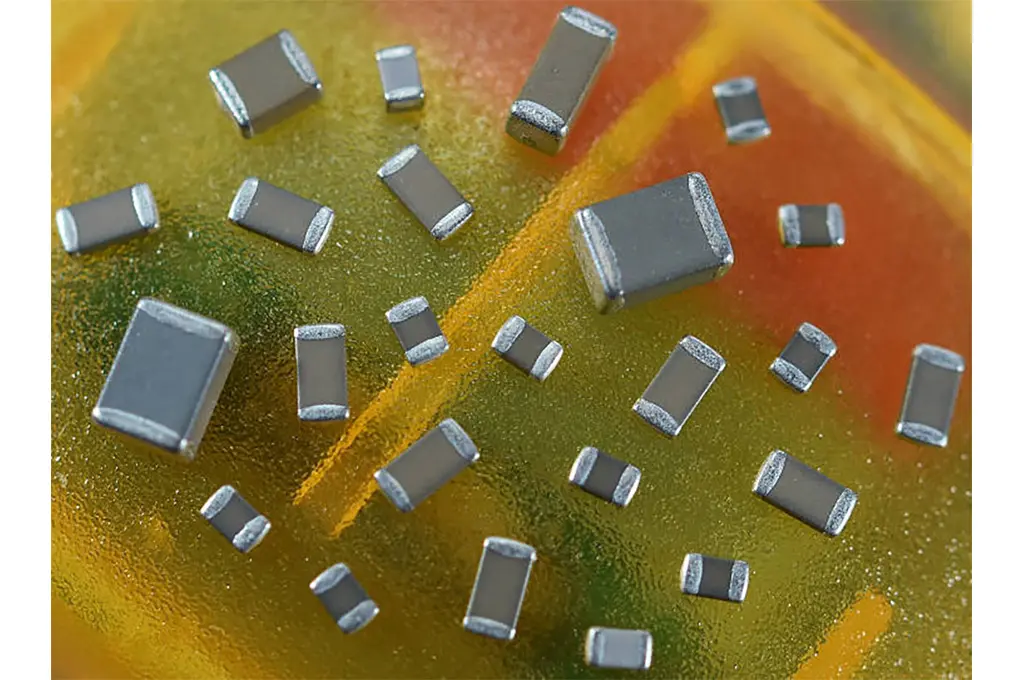
As automotive and industrial electronic modules move closer to heat sources, demand is increasing for MLCC dielectrics rated for operation up to +150°C.

There are several ceramic capacitor dielectrics families in regular use today: ultra-stable Class I types such as P90 (porcelain), NP0/C0G and U2J, alongside higher-capacitance Class II types such as X7R, X5R and Y5V.

RelatedPosts

Power Inductor Selection: Ferrite vs Powder Core Trade-Offs, Würth Elektronik Webinar

Bourns Releases Power Resistor Adds Reverse-Pin Configuration

DC-Link Film Capacitor Modules: Inductance and Thermal Design, Jianghai-Europe Tech Memo

With increasing use of electronic modules in under-the-hood applications in the automotive industry, X8* type ceramic dielectrics are also becoming more and more popular.

X8G, X8L and X8R are high-temperature ceramic dielectric designations for components intended to operate from -55°C to +150°C. In the Class II EIA code system, the first character defines the low-temperature limit, the second character the upper-temperature limit and the third character the allowed capacitance variation over that range. However, X8G is commonly used by manufacturers as a high-temperature Class I dielectric designation, while X8L and X8R are Class II characteristics.

Important note: X8R specifies a capacitance variation of ±15% from -55°C to +150°C. X8L allows a wider variation of +15% / -40% over the same coded temperature range. X8G is a stable Class I dielectric with a temperature coefficient commonly specified as 0 ±30 ppm/°C, but the exact manufacturer specification should always be checked.

DielectricDielectric classOperating temperature rangeCapacitance behaviour versus temperatureDC-bias and ageing sensitivityTypical use
X8GClass I-55°C to +150°CTypically 0 ±30 ppm/°C; check the individual manufacturer specificationVery low DC-bias effect; negligible ageingHigh-temperature precision, timing, resonant and filtering circuits
X8LClass II-55°C to +150°C+15% / -40% over the coded temperature range; commonly ±15% to +125°C, then +15% / -40% to +150°CPresent; verify with the part-specific datasheetHigh-temperature applications where higher capacitance density is needed and wider temperature variation is acceptable
X8RClass II-55°C to +150°C±15% over the coded temperature range, measured without applied DC voltageCan be significant; verify effective capacitance at applied DC voltageHigh-temperature decoupling, bypass and bulk-capacitance functions
X8G is a stable Class I dielectric; X8L and X8R are Class II dielectric characteristics with different allowed capacitance variation over temperature.

Why the difference matters in practice

X8G is a Class I dielectric, so it offers the best capacitance stability with temperature and also very low sensitivity to DC bias and ageing. The trade-off is its lower permittivity, which usually means lower achievable capacitance and lower CV in a given package size.

X8L and X8R are Class II dielectrics, so they are generally more attractive when higher capacitance density is needed at up to +150°C. However, designers should remember that effective capacitance in real circuits can be reduced by DC bias, ageing and operating conditions, especially for X8R parts with high nominal capacitance in small case sizes.

How to choose between X8G, X8L and X8R

  • Choose X8G when high-temperature capacitance stability, low loss and negligible DC-bias dependence are more important than maximum capacitance density. Typical applications include precision analogue, timing, resonant and filtering circuits.
  • Choose X8R when a predictable ±15% temperature characteristic through +150°C is required for decoupling, bypassing or bulk-capacitance functions. Check the manufacturer’s DC-bias curves to determine effective in-circuit capacitance.
  • Choose X8L only when its wider temperature characteristic of +15% / -40% is acceptable and the selected supplier offers the required capacitance, voltage rating, qualification and reliability level.

Important caveats for design engineers

  • The X8* code alone does not confirm automotive qualification. AEC-Q200 compliance, reliability grade, termination type and manufacturer-specific derating guidance must still be checked separately.
  • Two capacitors with the same X8R marking may behave quite differently under DC bias depending on capacitance value, rated voltage, case size and supplier technology.
  • Availability of X8G parts is typically narrower than X8L or X8R, especially at higher capacitance values.

Availability and qualification

X8R and X8L MLCCs are offered by several major manufacturers for high-temperature applications. X8G is less widely available and is generally limited to lower capacitance values than Class II alternatives. The dielectric code alone does not establish automotive qualification: verify AEC-Q200 status, voltage rating, reliability grade, termination system and manufacturer-specific derating guidance for the exact part number.

Dielectric designation is therefore a starting point for capacitor selection, not a complete prediction of in-circuit performance. Confirm final component selection using the manufacturer datasheet, temperature characteristic, DC-bias curve, ageing data and application-specific derating requirements.

featured image credit: Knowles
Related

Recent Posts

Würth Elektronik WE-LHMI and WE-HCI power inductor comparison slide showing current ratings and maximum operating temperatures

Power Inductor Selection: Ferrite vs Powder Core Trade-Offs, Würth Elektronik Webinar

3.11.2026
18
Bourns PWR163 DPAK-style surface-mount power resistor with moulded housing, metal backplate and terminals

Bourns Releases Power Resistor Adds Reverse-Pin Configuration

3.11.2026
2
Conceptual polypropylene DC-link film capacitor module with parallel cells and copper interconnections

DC-Link Film Capacitor Modules: Inductance and Thermal Design, Jianghai-Europe Tech Memo

3.11.2026
6

Motor Run Capacitor Safety Classes S0–S3: A Design Guide

2.11.2026
19

Elektra Awards 2026: Passive Components and Interconnect Finalists Showcase Advances in Power Integrity, Precision and Reliability

28.10.2026
51
Mathematical state-space illustration of a series-connected memcapacitor oscillator with two constrained memory coordinates

Memcapacitor chaos in a six-state series-connected model

28.10.2026
19
Exxelia capacitor and magnetics innovations for Electronica 2026, including CM-HVLP and CF-PP140 capacitors

Exxelia Brings High-Temperature Passives to Electronica 2026

29.10.2026
33

IP&E Market Outlook: AI Demand Tightens Supply and Supports Higher Pricing into 2027

28.10.2026
63
Samsung Electro-Mechanics CL05Z106MS66PN automotive MLCC illustration with a rectangular ceramic body and metal end terminations

Samsung Adds 0402 10 µF X7T MLCC for ADAS Power Rails

27.10.2026
23

Upcoming Events

Nov 24
16:00 - 17:00 CET

Select the Correct Components for Your DC/DC Converter

Dec 1
16:00 - 17:00 CET

Developing low-noise mixed-signal systems

Dec 8
16:00 - 17:00 CET

WE-CCMF: Design Principles, Layout Guidelines and Measurement Results for High-Speed EMI Filtering

View Calendar

Popular Posts

  • Buck Converter Design and Calculation

    0 shares
    Share 0 Tweet 0
  • Boost Converter Design and Calculation

    0 shares
    Share 0 Tweet 0
  • September 2026 Interconnect, Passives and Electromechanical Components Market Insights

    0 shares
    Share 0 Tweet 0
  • LLC Resonant Converter Design and Calculation

    0 shares
    Share 0 Tweet 0
  • Capacitor Charging and Discharging

    0 shares
    Share 0 Tweet 0
  • Flyback Converter Design and Calculation

    0 shares
    Share 0 Tweet 0
  • RF Connector Types: How To Choose the Right One

    0 shares
    Share 0 Tweet 0
  • Passive Low Pass Filters: Fundamentals and EMI Design

    0 shares
    Share 0 Tweet 0
  • MLCC and Ceramic Capacitors

    0 shares
    Share 0 Tweet 0
  • Audio Capacitors: Choosing Capacitors for Crossover Circuits

    0 shares
    Share 0 Tweet 0

Newsletter Subscription


Passive Components Blog

© 2015–2026
All rights reserved

  • Home
  • Privacy Policy
  • EPCI Membership & Advertisement
  • About

No Result
View All Result
  • Home
  • Knowledge Blog
  • Dossiers
  • PCNS

© 2015–2026
All rights reserved