Passive Components Blog
No Result
View All Result
  • Home
  • NewsFilter
    • All
    • Aerospace & Defence
    • Antenna
    • Applications
    • Automotive
    • Capacitors
    • Circuit Protection Devices
    • electro-mechanical news
    • Filters
    • Fuses
    • Inductors
    • Industrial
    • Integrated Passives
    • inter-connect news
    • Market & Supply Chain
    • Market Insights
    • Medical
    • Modelling and Simulation
    • New Materials & Supply
    • New Technologies
    • Non-linear Passives
    • Oscillators
    • Passive Sensors News
    • Resistors
    • RF & Microwave
    • Telecommunication
    • Weekly Digest

    Würth Elektronik Releases Long Life SMT nano and microSD Card Connectors

    Glass Core Technology Breakthrough Potential for High-Speed Interconnects

    YAGEO Releases High Isolation Transformer for 1500VDC Applications

    Bourns Releases 1500VDC Power Fuse for Photovoltaic Applications

    Murata Releases Worlds First Molded Thermistor with Wire-Bonding

    Vishay Extends Axial Wirewound Resistors with WSZ Lead Form

    Smoltek CNF-MIM Capacitor Commercialization Update

    Bourns Unveils Automotive Thick Film on Steel

    TT Electronics Releases Failsafe and High Surge SMD MELF Resistors

    Trending Tags

    • Ripple Current
    • RF
    • Leakage Current
    • Tantalum vs Ceramic
    • Snubber
    • Low ESR
    • Feedthrough
    • Derating
    • Dielectric Constant
    • New Products
    • Market Reports
  • VideoFilter
    • All
    • Antenna videos
    • Capacitor videos
    • Circuit Protection Video
    • Filter videos
    • Fuse videos
    • Inductor videos
    • Inter-Connect Video
    • Non-linear passives videos
    • Oscillator videos
    • Passive sensors videos
    • Resistor videos

    Understanding Switched Capacitor Converters

    Coupled Inductors Circuit Model and Examples of its Applications

    Inductor Resonances and its Impact to EMI

    Highly Reliable Flex Rigid PCBs, Würth Elektronik Webinar

    Causes of Oscillations in Flyback Converters

    How to design a 60W Flyback Transformer

    Modeling and Simulation of Leakage Inductance

    Power Inductor Considerations for AI High Power Computing – Vishay Video

    Coupled Inductors in Multiphase Boost Converters

    Trending Tags

    • Capacitors explained
    • Inductors explained
    • Resistors explained
    • Filters explained
    • Application Video Guidelines
    • EMC
    • New Products
    • Ripple Current
    • Simulation
    • Tantalum vs Ceramic
  • Knowledge Blog
  • Suppliers
    • Who is Who
  • Events
No Result
View All Result
Passive Components Blog
No Result
View All Result

A Low-Cost Capacitor Characterization System

10.3.2021
Reading Time: 7 mins read
A A

Signal Integrity Journal published an article proposing a low cost capacitor characterization system authored by Eric Bogatin, Sakshi Ranjan, Yash Shah, Jeff Cain, and Joe Hock.

Measuring low impedance components with a 2-port vector network analyzer (VNA) is an essential and very well-known technique [1]. Traditionally, it requires a VNA that costs more than $20,000. In our work, we used a new VNA, available for less than $500, for low impedance component characterization. This article describes our experience measuring an multi-layer ceramic capacitor (MLCC) and fitting models using this low-cost VNA and an open-source simulation tool.

RelatedPosts

Würth Elektronik Releases Long Life SMT nano and microSD Card Connectors

Glass Core Technology Breakthrough Potential for High-Speed Interconnects

YAGEO Releases High Isolation Transformer for 1500VDC Applications

Low-Cost VNAs

The VNA is the go to instrument for measuring the S-parameters of interconnect structures. There are many new lost-cost VNA instruments from companies such as Copper Mountain, National Instruments, and Picotech. But their price points are still above $5,000, which is a little outside a typical engineer’s personal budget.

One instrument stands out at a price point below $500. The DG8SAQ VNWA 3, from SDR Kits [2], only has a frequency range from 1 kHz to 1.3 GHz, but costs $450. It was developed for ham radio operators wanting to measure the transfer function of antennas or the impedance profile of their components. The company founder, Jan Verduyn, is a licensed amateur with callsign G5BBL. The DG8SAQ in the VNWA’s product name is the callsign of the instrument’s designer, Tom Baier.  

The DG8SAQ VNWA 3 is a 2-port VNA. The early model, the 3E, is capable of only an S11 and S21 measurement. This means that while it has 2-ports, it only measures in the forward direction. The latest model, the VNWA 3SE, is capable of fully automatic 2-port measurements.  While they can both be calibrated with traditional SOLT standards, SDR Kits recently introduced an ecal unit, the Magi-Cal, which is compatible with both instruments.

This is not a toy. Within its limited frequency range, it has impressive specs. There is a built-in frequency synthesizer that can sweep over a narrow or wide frequency range. It is limited to about 1000 frequency points. While the spec is listed as 90 dB dynamic range below 500 MHz and 50 dB above 500 MHz, we have measured better performance than this in our unit.

With a frequency limit to only 1.3 GHz, it would seem to be way too low for signal integrity applications where signal frequencies extend well into the 25 GHz range and above. What value could this VNA possibly offer in high speed digital applications?

The VNWA 3 Sweet Spot in PDN Applications

Figure 1. The complete system with the VNWA and fixture board with a selection of structures and capacitors.

The real value of the VNWA 3 with its 1 kHz to 1.3 GHz range is low impedance measurements for PDN applications. It is capable of a log frequency sweep. This means it can easily cover the 10 kHz to 1 GHz range. This is perfect for measuring the impedance profile of components and interconnects used in the power distribution path.

The 2-port shunt method using this VNWA with a log frequency sweep is the perfect application. To measure capacitors, for example, we want to measure a large dynamic range in impedance, from sub milliohm to >1k ohm, especially at high frequency.

But, just a VNWA is not enough. For simple, reliable, and routine capacitor characterization we need the VNA, a fixture board on which to place the capacitors and software to analyze the measurement.

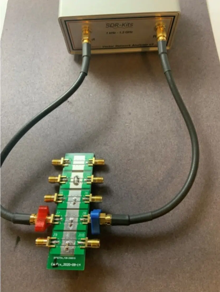
The fixture boards to interface the capacitors under test to the two ports of the VNA is a simple 2-layer board with SMA connectors on the ends. An open-source software tool to analyze these S-parameter measurements is Quite Universal Circuit Simulation (QUCS) [3]. Figure 1 shows an example of the complete system with a fixture board and the VNWA.

The 2-port Shunt Low Impedance Method

When measuring very low impedances, the 2-port shunt method is the standard process used in the industry. In this technique, the two ports are connected together and the component under test is connected between the signal pins of the two ports and their adjacent ground.

This is similar to the 4-wire Kelvin method. Effectively, port 1 drives the current while port 2 measures the voltage. The complex impedance of the device under test, ZDUT, is

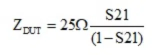
The VNA measures S21 across the specified frequency range. The measured S21 can be brought into QUCS, this conversion performed, and the magnitude, phase, or even real part of the impedance can be calculated and displayed.

 Since QUCS is a full featured SPICE like simulator, the measured impedance profiles can be compared with simple RLC models to fit and extract parameter values.

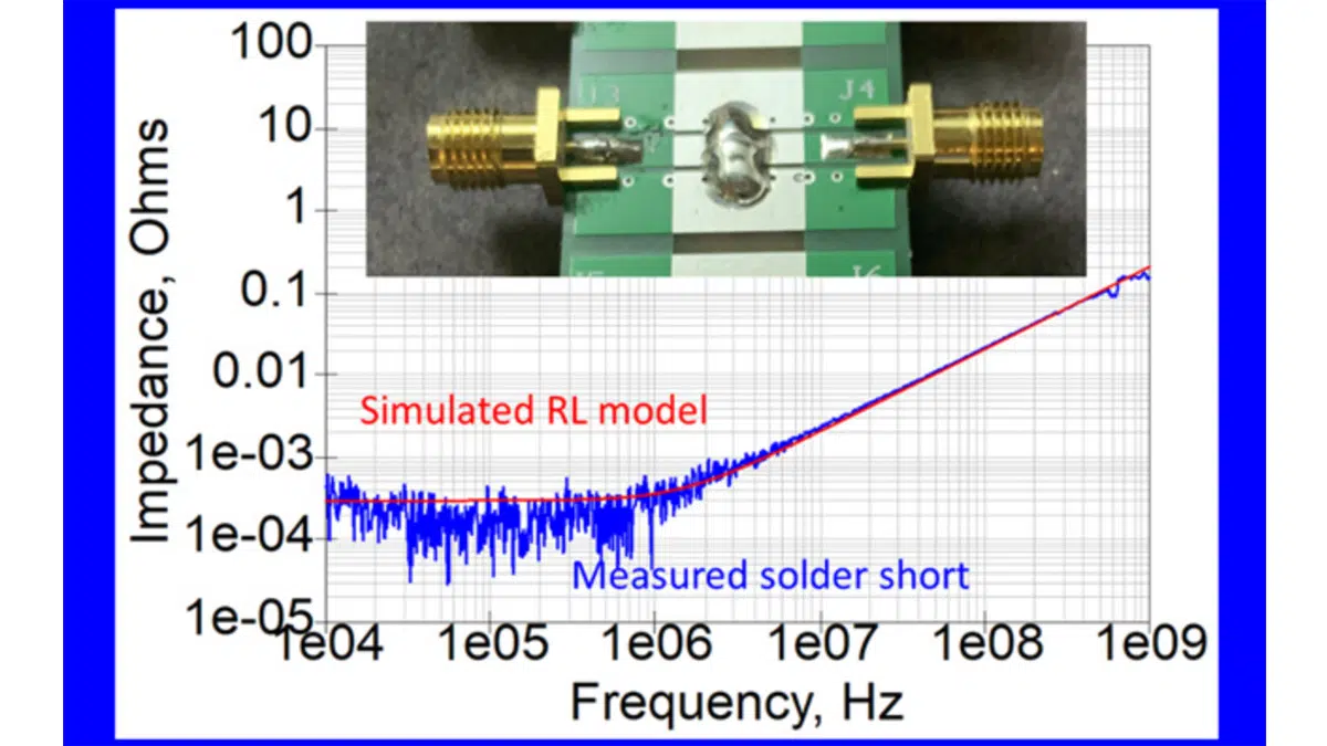
An interesting test of the capabilities of this measurement system is how low an impedance can be measured. As the test case, a blob of solder was added to short the signal and its adjacent return. The width of the solder blob was about 250 mils, about 4x the width of the 1206 component. Figure 2 shows the measured impedance with the fitted RL model for this test case.

Figure 2. The measured impedance and fitted impedance of an RL model for a solder short.

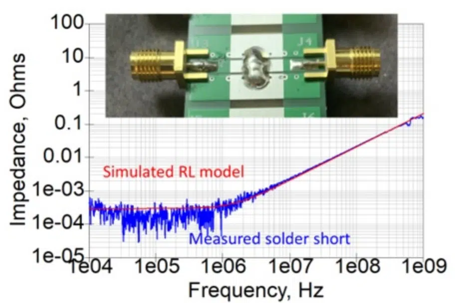
In this example, the fitted model matches the measurement with an R = 0.25 mOhms and L = 0.033 nH.

This demonstrates that this simple, low-cost measurement system is capable of 0.25 mOhm resistance and 33 pH of mounting inductance. The actual limit may be lower. These values are probably real measurements of the ESR and ESL of this solder blob.

The Myth of Three Capacitor Values

It is often erroneously reported that a 1 uF capacitor is a higher frequency capacitor than a 10uF or 47 uF [4]. This is based on the assumption that you are using through-hole, leaded capacitors, where the ESL is about the physical size of the capacitor.

With surface-mount device (SMD) capacitors, it is possible to get a 0.1 uF and 47 uF capacitor in the same body size which would have the same ESL. This is clearly demonstrated when comparing the measured impedance profile of three different capacitors, each with the identical 1206 body size and attached to the test fixture in a nearly identical fashion.

Figure 3 shows the measured impedance of a 1 uF, a 10 uF, and a 47 uF capacitor. While their impedances are very different at low frequency, above 10 MHz, in this example, their impedances are identical. A 47 uF capacitor is just as good a high frequency capacitor as a 1 uF capacitor. Low mounting inductance is the most important selection criteria for decoupling capacitors. If the costs are comparable, a 47 uF capacitor offers better performance at low frequency than a 0.1 uF capacitor, but just as good high frequency performance, contrary to many reference designs.

Figure 3. The measured impedance of three different capacitors with the same body size, compared to the impedance of a 0.7 nH ideal inductor.

Summary

A very simple, low-cost measurement system can be used to measure and characterize many passive two terminal components. This system is capable of measuring impedance below 1 mohm from frequencies from 10 kHz to 1 GHz. It is well suited for capacitor characterization. The combination of the low-cost VNA and the open-source, free simulator, QUCS, with simple, two-layer, low-cost fixture boards, makes this a system well within the personal budget of many engineers. Any lab interested in capacitor characterization should have this simple system.

References:

  1. Novak, Istvan. “Why 2-Port Low-Impedance Measurements Still Matter,” Signal Integrity Journal, January 2020. https://www.signalintegrityjournal.com/articles/1544-why-2-port-low-impedance-measurements-still-matter
  2. SDR-Kits Website. https://www.sdr-kits.net/index.php?route=common/home
  3. QUCS Website. http://qucs.sourceforge.net/
  4. Bogatin, Eric, Larry Smith, and Steve Sandler. “The Myth of Three Capacitor Values,” Signal Integrity Journal, March 2020. https://www.signalintegrityjournal.com/articles/1589-the-myth-of-three-capacitor-values

Acknowledgment

The authors from CU, Boulder, gratefully acknowledge the support of AVX Corp in completing this project.

Related

Source: Signal Integrity Journal

Recent Posts

Smoltek CNF-MIM Capacitor Commercialization Update

11.6.2025
7

Understanding Switched Capacitor Converters

9.6.2025
27

Exxelia to Present Smart Integrated Magnetics and MML Film Capacitors at SIAE25 

6.6.2025
28

What Track Width To Use When Routing PCB

6.6.2025
15

Knowles Extends Range and Performance of C0G MLCC Capacitors

6.6.2025
19

Panasonic Releases New Aluminum Hybrid Capacitors with High Ripple Current in Compact Size

6.6.2025
17

5th PCNS Conference Registration Now Open!

5.6.2025
21

YAGEO Introduces Automotive Supercapacitors for Stable BMS in EVs

5.6.2025
26

Capacitance Definition of Non-Linear Voltage Dependent Capacitors

5.6.2025
21

Passive Electronic Components Lead-times Update

4.6.2025
65

Upcoming Events

Jun 24
17:00 - 18:00 CEST

Ultra-Compact and Efficient Switched-Capacitor Power Converters

Jul 23
13:00 - 14:00 CEST

PCB design for a Smartwatch

View Calendar

Popular Posts

  • Buck Converter Design and Calculation

    0 shares
    Share 0 Tweet 0
  • Boost Converter Design and Calculation

    0 shares
    Share 0 Tweet 0
  • Flyback Converter Design and Calculation

    0 shares
    Share 0 Tweet 0
  • What is a Dielectric Constant and DF of Plastic Materials?

    4 shares
    Share 4 Tweet 0
  • LLC Resonant Converter Design and Calculation

    0 shares
    Share 0 Tweet 0
  • Ripple Current and its Effects on the Performance of Capacitors

    3 shares
    Share 3 Tweet 0
  • Dual Active Bridge (DAB) Topology Explained

    0 shares
    Share 0 Tweet 0
  • SEPIC Converter Design and Calculation

    0 shares
    Share 0 Tweet 0
  • How to Design an Inductor

    0 shares
    Share 0 Tweet 0
  • Flying Capacitors Explained

    0 shares
    Share 0 Tweet 0

Newsletter Subscription


Passive Components Blog

© EPCI - Leading Passive Components Educational and Information Site

  • Home
  • Privacy Policy
  • EPCI Membership & Advertisement
  • About

No Result
View All Result
  • Home
  • Knowledge Blog
  • Premium Suppliers

© EPCI - Leading Passive Components Educational and Information Site

This website uses cookies. By continuing to use this website you are giving consent to cookies being used. Visit our Privacy and Cookie Policy.
Go to mobile version