Passive Components Blog
No Result
View All Result
  • Home
  • NewsFilter
    • All
    • Aerospace & Defence
    • Antenna
    • Applications
    • Automotive
    • Capacitors
    • Circuit Protection Devices
    • electro-mechanical news
    • Filters
    • Fuses
    • Inductors
    • Industrial
    • Integrated Passives
    • inter-connect news
    • Market & Supply Chain
    • Market Insights
    • Medical
    • Modelling and Simulation
    • New Materials & Supply
    • New Technologies
    • Non-linear Passives
    • Oscillators
    • Passive Sensors News
    • Resistors
    • RF & Microwave
    • Telecommunication
    • Weekly Digest

    YAGEO Presents 3.6 kW LLC Transformer Platform

    Empower Extends Embedded Silicon Capacitors for AI

    ECIA February 2026 Industry Pulse Signals Strong Component Growth

    How Modern Tools Model Magnetic Components for Power Electronics

    Inductors and Ferrite Beads Price Hikes 

    TDK Extends Compact ThermoFuse Varistors up to 50 kA

    Samtec ANSI/VITA 90 Connectors: Rugged Small Form Factor Standard

    Resistor Technology Dossier

    Würth Elektronik IQD Awarded by EcoVadis Gold Sustainability Medal

    Trending Tags

    • Ripple Current
    • RF
    • Leakage Current
    • Tantalum vs Ceramic
    • Snubber
    • Low ESR
    • Feedthrough
    • Derating
    • Dielectric Constant
    • New Products
    • Market Reports
  • VideoFilter
    • All
    • Antenna videos
    • Capacitor videos
    • Circuit Protection Video
    • Filter videos
    • Fuse videos
    • Inductor videos
    • Inter-Connect Video
    • Non-linear passives videos
    • Oscillator videos
    • Passive sensors videos
    • Resistor videos

    How Modern Tools Model Magnetic Components for Power Electronics

    Advanced Loss Modeling for Planar Magnetics in the Frenetic Planar Tool

    2026 Power Magnetics Design Trends: Flyback, DAB and Planar

    Enabling Software‑Defined Vehicle Architectures: Automotive Ethernet and Zonal Smart Power

    Calculating Resistance Value of a Flyback RC Snubber 

    One‑Pulse Characterization of Nonlinear Power Inductors

    Thermistor Linearization Challenges

    Coaxial Connectors and How to Connect with PCB

    PCB Manufacturing, Test Methods, Quality and Reliability

    Trending Tags

    • Capacitors explained
    • Inductors explained
    • Resistors explained
    • Filters explained
    • Application Video Guidelines
    • EMC
    • New Products
    • Ripple Current
    • Simulation
    • Tantalum vs Ceramic
  • Knowledge Blog
  • DossiersNew
  • Suppliers
    • Who is Who
  • PCNS
    • PCNS 2025
    • PCNS 2023
    • PCNS 2021
    • PCNS 2019
    • PCNS 2017
  • Events
No Result
View All Result
Passive Components Blog
No Result
View All Result

Aluminium Capacitors Series Connection Balancing

30.10.2023
Reading Time: 3 mins read
A A

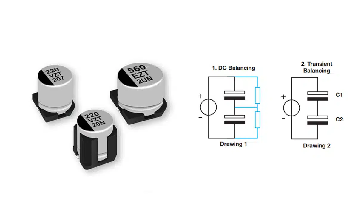
In the design of a capacitor bank, it is important to balance the capacitors for both DC and transient signal. This paper written by Vishay explains the balancing methods that applies to aluminum electrolytic capacitors.

If two capacitors are placed in series to a DC voltage source U, the midpoint-voltage is not automatically 0.5 x U. The voltage distribution is dominated by the leakage current, which varies by capacitor and is voltage-dependent. The capacitor that has the larger leakage current at 0.5 x U will have a somewhat smaller voltage drop than the other capacitor, leading to an equalized leakage current through both capacitors.

RelatedPosts

Vishay Unveils Ultra-Compact 0201 Thick Film Chip Resistors

Vishay Releases Sulfur‑Resistant Chip Resistors

Vishay Releases Compact 0806 Low‑DCR Power Inductor

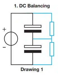
Depending on the difference in leakage current, this could lead to voltage drops larger than the rated voltage, which could result in decreased lifetime or even early failure. Balancing the DC voltage is therefore necessary. This can be done in a passive way as shown in Drawing 1: two resistors in parallel to the capacitors, with values typically calculated as Rmax = (2 x Umax. – U)/Ileak– 5min x Umax. would be the maximum allowable voltage drop across one capacitor (typically Urated). U is the applied DC voltage. Ileak-5min is the DC leakage current as measured after five minutes of applied rated voltage.

The disadvantage of this way of passive balancing is a relatively high efficiency loss, typically from 1 % to 5 %. This is unacceptable in applications like solar inverters, where the need for maximum efficiency dominates the market. Here designers work with active balancing.

Practical advice: if one of the capacitors in a series connection fails, replace both capacitors with two fresh ones from the same batch, to ensure that the leakage currents of both devices in one branch are roughly equal.

Two capacitors in series connected to a power source will react differently to transient signals. For the change in voltage drop over a capacitor, C1 holds ∆ V1 = 1/C1 ∫ I1(t)dt. With a fixed current (I=I1 =I2) running through C1 and C2, we get C1 ∆ V1 = C2*∆ V2, or ∆ V1/∆ V2 = C2/C1. So the change in midpoint voltage is determined by the ratio of the capacitances. This leads to simple requirements from designers: C1 = C2. This is correct from a theoretical point of view, but manufacturers of electrolytic capacitors work with a typical production variation of ± 20 % in capacitance in their specifications. This tolerance is set on all produced capacitors; within one batch, variation is less. Typically, the variation within one batch is ± 6 % (total spread from a minimum to maximum capacitance of 12 %).

Practical advice: use capacitors from the same production batch per individual branch. When switching to another production batch, one should measure the 100 Hz capacitance value of all capacitors in that specific branch to exclude unbalanced branches. The same holds for the replacement of capacitors at failure. Remove all capacitors from the branch and replace with fresh ones from the same batch.

Related

Source: Vishay

Recent Posts

Empower Extends Embedded Silicon Capacitors for AI

6.3.2026
9

AI Servers Demand is Driving Tantalum Capacitor Price Hikes

5.3.2026
76

DMASS Reports Europe Components Up 9.8% in Q4 2025

3.3.2026
21

Mastering Galvanic Isolation in Power Electronics: Methods, Standards, and Implementation

2.3.2026
35

VINATech Targets AI Data Center Supercapacitor Boom

26.2.2026
43

TDK Introduces 350V Safety Film Capacitors for Compact EMI Suppression

26.2.2026
36

Samsung Launches Worlds First Automotive 47uF 4V MLCC in 0805 Size

24.2.2026
37

Würth Elektronik Present in IEEE APEC

24.2.2026
19

Samsung Three Pillars MLCC Strategy for AI Hardware Topology

24.2.2026
95

Upcoming Events

Mar 19
13:00 - 14:00 CDT

Smart Consideration of Inductor Thermal Performance

Mar 21
All day

PSMA Capacitor Workshop 2026

Apr 21
16:00 - 17:00 CEST

Heatsink Solutions: Thermal Management in electronic devices

View Calendar

Popular Posts

  • Buck Converter Design and Calculation

    0 shares
    Share 0 Tweet 0
  • Boost Converter Design and Calculation

    0 shares
    Share 0 Tweet 0
  • Flyback Converter Design and Calculation

    0 shares
    Share 0 Tweet 0
  • LLC Resonant Converter Design and Calculation

    0 shares
    Share 0 Tweet 0
  • MLCC Manufacturers Consider Price Increase as AI Demand Outpaces Supply

    0 shares
    Share 0 Tweet 0
  • Dual Active Bridge (DAB) Topology

    0 shares
    Share 0 Tweet 0
  • Ripple Current and its Effects on the Performance of Capacitors

    3 shares
    Share 3 Tweet 0
  • MLCC and Ceramic Capacitors

    0 shares
    Share 0 Tweet 0
  • What is a Dielectric Constant and DF of Plastic Materials?

    4 shares
    Share 4 Tweet 0
  • MLCC Case Sizes Standards Explained

    0 shares
    Share 0 Tweet 0

Newsletter Subscription


Passive Components Blog

© EPCI - Leading Passive Components Educational and Information Site

  • Home
  • Privacy Policy
  • EPCI Membership & Advertisement
  • About

No Result
View All Result
  • Home
  • Knowledge Blog
  • PCNS

© EPCI - Leading Passive Components Educational and Information Site

This website uses cookies. By continuing to use this website you are giving consent to cookies being used. Visit our Privacy and Cookie Policy.
Go to mobile version