Passive Components Blog
No Result
View All Result
  • Home
  • NewsFilter
    • All
    • Aerospace & Defence
    • Antenna
    • Applications
    • Automotive
    • Capacitors
    • Circuit Protection Devices
    • electro-mechanical news
    • Filters
    • Fuses
    • Inductors
    • Industrial
    • Integrated Passives
    • inter-connect news
    • Market & Supply Chain
    • Market Insights
    • Medical
    • Modelling and Simulation
    • New Materials & Supply
    • New Technologies
    • Non-linear Passives
    • Oscillators
    • Passive Sensors News
    • Resistors
    • RF & Microwave
    • Telecommunication
    • Weekly Digest

    Bourns Releases High Current Metal Alloy-based, Multilayer Power Chip Inductors

    Smiths Interconnect Extends Space-Qualified, High-Reliability Fixed Chip Attenuators 

    Samtec Expands Offering of Slim, High-Density HD Array Connectors

    Bourns Unveils High-Precision Wirewound Resistor with Long-Term Stability

    Common Mode Chokes Selection for RF Circuits in Next-Generation Communication Systems

    Capacitor Self-balancing in a Flying-Capacitor Buck Converter

    Littelfuse Acquires Basler Electric Enhancing High-Growth Industrial Market

    DigiKey Grows Inventory with Over 31K New Stocking Parts in Q3 2025

    Murata Expands Automotive Metal Frame Y2/X1 Safety MLCC Capacitors to 500V

    Trending Tags

    • Ripple Current
    • RF
    • Leakage Current
    • Tantalum vs Ceramic
    • Snubber
    • Low ESR
    • Feedthrough
    • Derating
    • Dielectric Constant
    • New Products
    • Market Reports
  • VideoFilter
    • All
    • Antenna videos
    • Capacitor videos
    • Circuit Protection Video
    • Filter videos
    • Fuse videos
    • Inductor videos
    • Inter-Connect Video
    • Non-linear passives videos
    • Oscillator videos
    • Passive sensors videos
    • Resistor videos

    Common Mode Chokes Selection for RF Circuits in Next-Generation Communication Systems

    Capacitor Self-balancing in a Flying-Capacitor Buck Converter

    How to Select Ferrite Bead for Filtering in Buck Boost Converter

    Power Inductors Future: Minimal Losses and Compact Designs

    Percolation Phenomenon: Degradation of Molded Power Inductors in DC/DC Converters

    Connector PCB Design Challenges

    Efficient Power Converters: Duty Cycle vs Conduction Losses

    Ripple Steering in Coupled Inductors: SEPIC Case

    SEPIC Converter with Coupled and Uncoupled Inductors

    Trending Tags

    • Capacitors explained
    • Inductors explained
    • Resistors explained
    • Filters explained
    • Application Video Guidelines
    • EMC
    • New Products
    • Ripple Current
    • Simulation
    • Tantalum vs Ceramic
  • Knowledge Blog
  • Suppliers
    • Who is Who
  • PCNS
    • PCNS 2025
    • PCNS 2023
    • PCNS 2021
    • PCNS 2019
    • PCNS 2017
  • Events
No Result
View All Result
Passive Components Blog
No Result
View All Result

Calculating the Lifespan of Aluminum Electrolytic Capacitors with De-Rating

29.8.2022
Reading Time: 6 mins read
A A

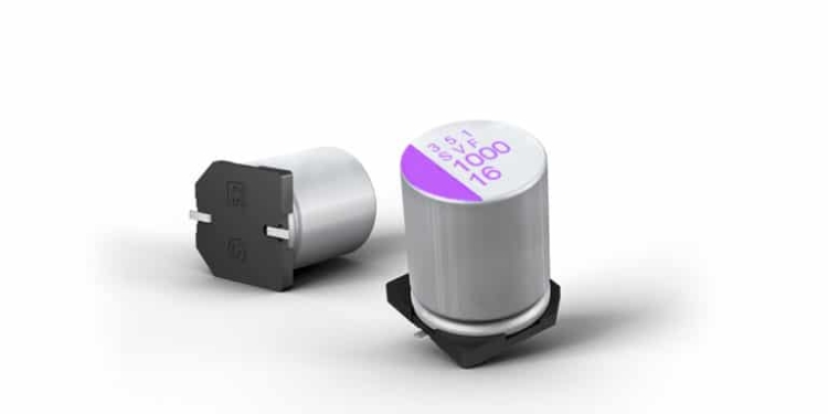
You may have heard that electrolytic capacitors are a bad choice. But how much of that bad rap is actually deserved? David Williams makes a case that electrolytic capacitors deserve another chance. Aluminum electrolytic capacitors have a reputation as having a short life expectancy and being unreliable. Part of that reputation is due to a fifteen-year-old stolen electrolyte formula scandal—but part of it is because they really don’t last as long as other types of capacitors. But are they really that much worse?

A Scandalous Reputation
In the early 2000s, aluminum electrolytic capacitors (Al e-caps) were failing at a far higher rate than expected. The cause was tracked down to an interesting story of industrial espionage where a formula for the electrolytic solution of the capacitors was stolen, but then incorrectly used. The result was millions of bad capacitors ending up in all sorts of electronic devices.

RelatedPosts

Bourns Releases High Current Metal Alloy-based, Multilayer Power Chip Inductors

Smiths Interconnect Extends Space-Qualified, High-Reliability Fixed Chip Attenuators 

Samtec Expands Offering of Slim, High-Density HD Array Connectors

This story certainly gave Al e-caps a bad reputation as unreliable parts, and this reputation is further enhanced by the fact that even properly manufactured Al e-caps have a relatively short lifespan when compared to film capacitors (which can also have high capacitance and high voltage ratings like Al e-caps).

For example, the KXG family of Al e-caps from United Chemi-Con (which includes capacitors with capacitances from 6.8μF to 330μF and voltage ratings from 160V-450VDC) has a rated life expectancy of 8,000 to 10,000 hours while the EPCOS B32798 family of film capacitors (which includes capacitors with capacitances from 18μF to 75μF and voltage ratings from 250V-400VDC) has a rated life expectancy of 60,000 hours.

It would appear that the reputation of Al e-caps as unreliable devices is actually justified. But is that actually the case?

Assessing the Lifespan of Components
To properly assess the lifespan of a component requires more than just looking at the rated lifespan. The effect of stresses (heat, current, voltage) that the device will undergo during operation also needs to be included in the analysis. It turns out that the rated lifespan is typically given for a case of fairly high stress.

If the device is going to be used at a lower temperature, voltage, or current, the rated lifespan can be de-rated. This de-rating involves re-calculating the lifespan based on the actual operating temperature, voltage, and current, and often times the de-rated lifespan is many times longer than the rated lifespan.

Manufacturers of capacitors will typically provide de-rating calculations or graphs based on their research and field testing. Often times, these calculations are not included in the component datasheet but are instead found in a separate capacitor characteristics document (the reason for this is that there is probably just too much extra information to include in a datasheet).

Defining Capacitor “Failure”
The first thing to determine from the manufacturer is how they define a failed capacitor. A failure is not usually defined as “doesn’t work anymore”—it is typically defined as a certain percentage change in the characteristics of the capacitor. This definition is important to know so that a proper comparison between capacitors can be made.

For example, Vishay uses standard CECC 30301 for their Al e-caps, which defines the end of life as being when the capacitance changes by 30%, the dissipation factor changes to more than three times the upper limit, or if the impedance is more than three times the stated limit. Meanwhile, TDK defines the end of life for their B32798 series film capacitors when the capacitance changes by 10%, the dissipation factor changes to more than four times the upper limit, or if the insulation resistance drops below 1500MΩ.

Defining Capacitor “De-Rating”
The second thing to determine from the manufacturer is how they de-rate the expected life of a component. In general, capacitors (and many other devices) can be de-rated as follows:

lifeactual=lifebase×temperatureFactor×voltageFactor×currentFactor

  • lifeactual is the life expectancy at the operating temperature, voltage, and current.
  • lifebase is the life expectancy at the rated temperature, voltage, and current
  • temperatureFactor: For both Al e-caps and film capacitors, a 10°C decrease in temperature results in a doubling of life expectancy. So the temperature factor is 20.1(Tm−Tc). Where Tm is the rated temp and Tc is the operating temp.
  • voltageFactor is the derating due to the operating voltage being lower than the maximum rated voltage. According to United Chemi-Con, voltage has far less of an effect than temperature on the lifespan of an Al e-cap (unless the voltage is exceeding the rated maximum)
  • currentFactor is the derating due to the operating current being lower than the maximum rated current. Current has a more significant effect on Al e-caps than film capacitors because of their higher equivalent series resistance (ESR). The power loss due to the ESR will be equal toI2capRESR
    and all of this power loss leads to self heating which will affect lifespan.

Applying Lifespan Calculations: An Example of Capacitor Selection
Armed with this de-rating equation and the de-rating factors, it is possible to do a proper lifespan comparison between capacitors. To illustrate the comparison, let’s look at a specific example.

Assume that we are designing an AC-DC converter for a battery charging system. This battery system operates at 400VDC and we have determined that we need a 300μF capacitor for the filter of the converter. After some research to find components that meet these voltage and capacitance requirements and also have the best combination of size and cost, we find two possible solutions.

We could use three 100μF Al e-caps from United Chemi-Con (part number EKXG451ELL101MM40S) or four 75μF film capacitors from EPCOS (part number B32798G2756K). The tradeoff between these two selections is that the Al e-caps will cost about $10 total but have a rated lifespan of 10,000 hours, while the film capacitors will cost about $120 total but have a rated lifespan of 60,000 hours.

If we need this battery charger to last at least four years, it appears that we will have to select the far more expensive option.

De-Rating to the Rescue
But wait! We don’t have to use this rated life expectancy because this system is going to operate below the rated temperature and voltage of the devices. This means we can de-rate the life expectancy and end up with a longer life at the operating temperature and voltage than the rated life.

Once again, the lifespan de-rating calculation is

lifeactual=lifebase×temperatureFactor×voltageFactor×currentFactor
For simplicity, let’s assume the voltage factor and the current factor are both 1 (they are both probably more than 1) and only de-rate based on temperature. If the actual life calculated is still not long enough, we can determine what the actual voltage and current factors are to provide an even more accurate expected lifespan.

Both of the capacitors have a temperature rating of 105°C, so if the operating temperature is estimated at 75°C (which is high for this system), there is a 30°C difference between the rated and the operating temperature.

This 30°C difference results in three doublings of the expected lifespan over the rated lifespan. In other words, the actual expected lifespan will be 2^3=8 times more than the rated lifespan. For the Al e-cap, this means that the expected life will actually be 80,000 hours which is just over 9 years of continuous operation.

Conclusion
Al e-caps have a reputation as unreliable parts with a short lifespan. This reputation is justified if you are only looking at the rated lifespan, but the operating conditions are often much more favorable than the rated conditions.

These better conditions mean that the lifespan estimation can actually be increased (de-rated). With proper selection of components (paying attention to rated temperature, voltage, and current), it is possible to select components that have actual lifespans that are much higher than their rated lifespans. This lifespan de-rating can allow us to find Al e-cap components that can actually meet the life expectancy requirements for most systems.

Related

Recent Posts

Samtec Expands Offering of Slim, High-Density HD Array Connectors

30.10.2025
9

Bourns Unveils High-Precision Wirewound Resistor with Long-Term Stability

30.10.2025
14

Capacitor Self-balancing in a Flying-Capacitor Buck Converter

30.10.2025
12

Murata Expands Automotive Metal Frame Y2/X1 Safety MLCC Capacitors to 500V

30.10.2025
21

Exxelia 4-Terminal Safety Capacitors Compliant with NF F 62-102 Railway Standard

27.10.2025
27

Samsung Releases Automotive Molded 2220 1kV C0G MLCC

23.10.2025
52

VINATech Offers Smallest 100µF Al-Hybrid Capacitor

23.10.2025
43

Vishay Unveils SMD 1200V PTC Thermistors in Compact Size

23.10.2025
11

Bourns Unveils Automotive 3 Watt Gate Driver Transformer

22.10.2025
9

Murata Integrates Component Models into Cadence EDA Tools

21.10.2025
48

Upcoming Events

Nov 4
10:00 - 11:00 PST

Design and Stability Analysis of GaN Power Amplifiers using Advanced Simulation Tools

Nov 4
November 4 @ 12:00 - November 6 @ 14:15 EST

Wirebond Materials, Processes, Reliability and Testing

Nov 6
14:30 - 16:00 CET

Self-healing polymer materials for the next generation of high-temperature power capacitors

View Calendar

Popular Posts

  • Buck Converter Design and Calculation

    0 shares
    Share 0 Tweet 0
  • Boost Converter Design and Calculation

    0 shares
    Share 0 Tweet 0
  • LLC Resonant Converter Design and Calculation

    0 shares
    Share 0 Tweet 0
  • Flyback Converter Design and Calculation

    0 shares
    Share 0 Tweet 0
  • Ripple Current and its Effects on the Performance of Capacitors

    3 shares
    Share 3 Tweet 0
  • MLCC and Ceramic Capacitors

    0 shares
    Share 0 Tweet 0
  • Dual Active Bridge (DAB) Topology

    0 shares
    Share 0 Tweet 0
  • SEPIC Converter Design and Calculation

    0 shares
    Share 0 Tweet 0
  • What is a Dielectric Constant and DF of Plastic Materials?

    4 shares
    Share 4 Tweet 0
  • Flying Capacitors

    0 shares
    Share 0 Tweet 0

Newsletter Subscription


Passive Components Blog

© EPCI - Leading Passive Components Educational and Information Site

  • Home
  • Privacy Policy
  • EPCI Membership & Advertisement
  • About

No Result
View All Result
  • Home
  • Knowledge Blog
  • PCNS

© EPCI - Leading Passive Components Educational and Information Site

This website uses cookies. By continuing to use this website you are giving consent to cookies being used. Visit our Privacy and Cookie Policy.
Go to mobile version