Passive Components Blog
No Result
View All Result
  • Home
  • NewsFilter
    • All
    • Aerospace & Defence
    • Antenna
    • Applications
    • Automotive
    • Capacitors
    • Circuit Protection Devices
    • electro-mechanical news
    • Filters
    • Fuses
    • Inductors
    • Industrial
    • Integrated Passives
    • inter-connect news
    • Market & Supply Chain
    • Market Insights
    • Medical
    • Modelling and Simulation
    • New Materials & Supply
    • New Technologies
    • Non-linear Passives
    • Oscillators
    • Passive Sensors News
    • Resistors
    • RF & Microwave
    • Telecommunication
    • Weekly Digest

    Würth Elektronik Expands Nanocrystalline Cable Cores for Broadband EMI Suppression

    High‑Speed Supercapacitor Balancing for AI Data Center Power Systems

    Bourns Introduced Automotive TVS Diodes for Compact ESD Protection

    EMC‑Compliant PCB and Connector Design Guidelines

    Practical Value of Structural Diagnostics for Tantalum Capacitor Anodes

    Hall-Effect Sensing for Harsh Environments: TT Electronics Selected in NASA’s Dragonfly Fan

    Bourns Releases Automotive Gate Driver Transformer for Isolated Power

    Stackpole Releases High-Frequency Thin Film Chip Resistors for RF up to 50 GHz

    Knowles Expands High‑Q Ceramic Core Inductors for RF designs

    Trending Tags

    • Ripple Current
    • RF
    • Leakage Current
    • Tantalum vs Ceramic
    • Snubber
    • Low ESR
    • Feedthrough
    • Derating
    • Dielectric Constant
    • New Products
    • Market Reports
  • VideoFilter
    • All
    • Antenna videos
    • Capacitor videos
    • Circuit Protection Video
    • Filter videos
    • Fuse videos
    • Inductor videos
    • Inter-Connect Video
    • Non-linear passives videos
    • Oscillator videos
    • Passive sensors videos
    • Resistor videos

    EMC‑Compliant PCB and Connector Design Guidelines

    Why Isolated DC/DC Power Supplies Fail Late, Würth Elektronik Podcast

    Designing 800 V DC EMC Filters: Calculation, Simulation and Measurement

    Current Sense Transformer Datasheet and Design‑in Guide

    Designing a USB Type‑C Flyback Planar Transformer with Frenetic’s Planar Tool

    Magnetics Design in High‑Frequency GaN Converters

    Qi2 Wireless Charging: Inductors, Capacitors and EMC Filters

    Two‑capacitor paradox explained for engineers

    Capacitances of Nonlinear MLCCs: What Datasheets Don’t Tell You

    Trending Tags

    • Capacitors explained
    • Inductors explained
    • Resistors explained
    • Filters explained
    • Application Video Guidelines
    • EMC
    • New Products
    • Ripple Current
    • Simulation
    • Tantalum vs Ceramic
  • Knowledge Blog
  • DossiersNew
  • Suppliers
    • Who is Who
  • PCNS
    • PCNS 2025
    • PCNS 2023
    • PCNS 2021
    • PCNS 2019
    • PCNS 2017
  • Events
No Result
View All Result
Passive Components Blog
No Result
View All Result

Best Practices for Cable Management in High-Speed and High-Density Systems

4.9.2025
Reading Time: 5 mins read
A A
source: Samtec

source: Samtec

This paper based on post Samtec’s Cable Management in High‑Data‑Rate Applications offering a cbrief framework for engineers, technicians, and system integrators about the best practices for cable management in high-speed and high-density systems.

In the era of high‑data‑rate (HDR) and high‑speed electronic systems, cable management has evolved from a tidy‑up exercise into a critical engineering discipline. The way cables are routed, bent, twisted, labeled, and secured can have a measurable effect on signal integrity, thermal performance, and long‑term reliability.

RelatedPosts

Samtec AcceleRate Slim ARC6 Cable Assemblies with New Signaling Options

Samtec ANSI/VITA 90 Connectors: Rugged Small Form Factor Standard

Key Interconnect Technologies for 2025

1. Introduction

As data rates climb into the tens and hundreds of gigabits per second, the physical layer becomes increasingly sensitive to mechanical handling. A poorly routed cable can introduce impedance discontinuities, skew, and crosstalk, while also restricting airflow and creating serviceability headaches. In high‑density environments such as AI accelerators, hyperscale data centers, and advanced test systems, the stakes are even higher: downtime is costly, and rework is disruptive.

Cable management, therefore, is not just about aesthetics. It is about preserving the electrical and mechanical integrity of the interconnect over the system’s operational life. This requires a disciplined approach that considers bend radius, twist control, strain relief, slack allocation, labeling, and structured routing — all while anticipating future maintenance and upgrades.

2. Bend and Twist: The Mechanics of Signal Integrity

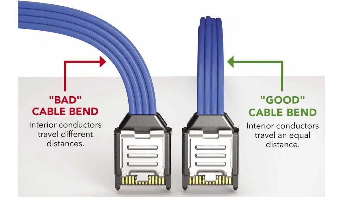
One of the most overlooked aspects of cable management is the geometry of bends and twists. Samtec’s guidance highlights a subtle but critical distinction between a “good” bend and a “bad” bend. In a good bend, the conductors inside the cable remain at consistent lengths, preserving timing alignment. In a bad bend — often caused by bending along the connector’s length — the inner and outer conductors travel different distances, introducing skew and degrading high‑speed performance.

The recommended practice is to first bend the cable in the optimal direction, then apply a controlled 90‑degree twist along the connector length. This twist should not be forced; instead, it should follow the cable’s natural lay, which is easier to achieve when cables are loosely bundled rather than tightly bound. Over‑tight bundling not only resists proper twisting but also increases mechanical stress and can deform the dielectric, altering impedance.

3. Stress Relief at Cable Exits

The point where a cable exits a connector is a mechanical weak spot. Sharp bends here can transfer stress directly to the termination, leading to intermittent faults or outright failure. Allowing cables to splay outward before routing them into a bend distributes mechanical load more evenly. This technique also enables tighter bend radii without exceeding the cable’s minimum bend specification, which is especially important for twinax and coax assemblies used in HDR applications.

4. Slack Management: Balancing Flexibility and Order

Slack is both a necessity and a liability. Too little slack, and cables may be strained during servicing or thermal expansion; too much, and they form loops that obstruct airflow and create clutter. The goal is to provide just enough slack to allow for connector mating/demating and minor re‑routing, while keeping the overall path taut and predictable. Horizontal and vertical cable managers, Velcro straps (preferred over zip ties for reusability and reduced compression), and modular routing panels can help maintain this balance.

5. Identification and Documentation

In complex systems, the time spent tracing an unmarked cable can dwarf the time spent replacing it. Industry standards such as ANSI/TIA‑606 recommend labeling both ends of every cable with durable, legible identifiers. Color coding can further speed identification, especially when differentiating between copper, fiber, and power lines. Beyond physical labels, maintaining an up‑to‑date cable map — ideally in a DCIM (Data Center Infrastructure Management) system or CAD model — ensures that changes are tracked and future work is streamlined.

6. Structured Routing and Pathways

Structured cabling principles apply equally inside a chassis as they do in a data hall. Separating power and data cables reduces electromagnetic interference (EMI) risk, while dedicated trays, raceways, and runways prevent accidental damage. For high‑density racks, it is wise to design pathways with 30–40% spare capacity to accommodate future expansion without re‑routing existing cables. Fiber optic cables, in particular, require careful routing to avoid microbending losses.

7. Thermal and Electrical Performance Considerations

Cable bundles can act as thermal insulators, trapping heat around active components. This is especially problematic in systems with high‑power GPUs, FPGAs, or CPUs, where every degree of cooling margin matters. Over‑bundling can also increase insertion loss by compressing the dielectric. Engineers should route cables to preserve airflow channels and, where possible, use perforated managers or open‑frame trays to promote convection.

From an electrical standpoint, improper bends or excessive mechanical stress can alter the characteristic impedance of high‑speed cables, leading to reflections and jitter. In HDR systems, even small impedance mismatches can cause measurable eye‑diagram closure, reducing link margin.

8. Standards and Compliance

Adhering to established standards ensures consistency and interoperability. ANSI/TIA‑606 provides a framework for labeling and administration, while TIA‑942 outlines best practices for data center cabling infrastructure. For product‑specific handling, always consult the manufacturer’s datasheets for parameters such as static and dynamic bend radius, flex life, and mating cycles.

9. Summary and Conclusion

  • Consistent conductor lengths: Good bends keep all conductors on equal-length paths; bad bends force different path lengths and add skew.
  • Bend plane vs connector plane: Good bends occur after the exit, in a single plane; bad bends “wrap” along the connector length.
  • Bend-then-twist sequencing: Bend first, then apply a controlled 90° twist along the cable’s axis—not at the exit or through the connector.
  • Stress relief at exits: Allow cable fan-out before routing; do not force tight turns immediately at the termination.
  • Minimum bend radius: Honor datasheet values; when unspecified, use conservative planning like ≥10×OD for copper and fiber-safe radii for optics.
  • Bundle pressure: Use low-compression ties (hook-and-loop), avoid over-tightening that deforms dielectric or jacket.

Cable management in high‑speed and high‑density environments is a convergence of mechanical engineering, electrical design, and operational foresight. By applying disciplined bend and twist techniques, relieving stress at exits, managing slack intelligently, labeling rigorously, and routing with structure, engineers can safeguard performance and reliability while simplifying maintenance. As data rates continue to climb, these practices will only grow in importance — transforming cable management from an afterthought into a core design consideration.

Related

Source: Samtec

Recent Posts

EMC‑Compliant PCB and Connector Design Guidelines

22.6.2026
23

Hirose Releases Ultra‑low Profile FPC‑to‑board Connector

17.6.2026
13

Molex Expanded AirBorn SInergy Hybrid Connectors with 25 A Power Modules

16.6.2026
22

Hirose Releases 0.5 mm Floating Board-to-Board Connector for EV Powertrain Designs

15.6.2026
11

Hirose Expands Compact High‑Voltage EV connectors

21.5.2026
48

YAGEO Releases Compact RJ45 Connector for Multi‑Gigabit Ethernet

18.5.2026
42

Binder Hybrid Connector Simplifies One Cable Automation

13.5.2026
40

binder Releases Tool‑Tightenable M12 Connectors for Improved Reliability

30.4.2026
32

Kyocera Developed Multilayer Ceramic Core Substrate for AI Packages

30.4.2026
149

Upcoming Events

Jun 30
17:00 - 18:00 CEST

PSMA Capacitor Committee Webinar: High Voltage Pulse Capacitors

Jul 14
16:00 - 17:00 CEST

EMC Design Essentials: Mastering Varistors and Common Mode Chokes

Jul 21
16:00 - 17:00 CEST

Safety by design: X and Y Interference suppression capacitors for power line filters

View Calendar

Popular Posts

  • Boost Converter Design and Calculation

    0 shares
    Share 0 Tweet 0
  • Buck Converter Design and Calculation

    0 shares
    Share 0 Tweet 0
  • LLC Resonant Converter Design and Calculation

    0 shares
    Share 0 Tweet 0
  • Flyback Converter Design and Calculation

    0 shares
    Share 0 Tweet 0
  • MLCC and Ceramic Capacitors

    0 shares
    Share 0 Tweet 0
  • Earthing Systems and IEC Classification Explained

    0 shares
    Share 0 Tweet 0
  • Nvidia Vera Rubin: Why One AI Rack Needs So Many More MLCC Capacitors

    0 shares
    Share 0 Tweet 0
  • Dual Active Bridge (DAB) Topology

    0 shares
    Share 0 Tweet 0
  • SEPIC Converter Design and Calculation

    0 shares
    Share 0 Tweet 0
  • MLCC Case Sizes Standards Explained

    0 shares
    Share 0 Tweet 0

Newsletter Subscription


Passive Components Blog

© EPCI - Leading Passive Components Educational and Information Site

  • Home
  • Privacy Policy
  • EPCI Membership & Advertisement
  • About

No Result
View All Result
  • Home
  • Knowledge Blog
  • Dossiers
  • PCNS

© EPCI - Leading Passive Components Educational and Information Site

This website uses cookies. By continuing to use this website you are giving consent to cookies being used. Visit our Privacy and Cookie Policy.
Go to mobile version