


This paper focuses on EMI suppression film capacitors requirements in xEV systems that must be addressed (additionally) for EMI suppression capacitors, such as: parameter drift, operation voltage vs. temperature, high-voltage testing, current distribution, parasitic inductance, AEC-Q200[2], mounting and soldering heat, etc., and introduces the latest product range of TDK EMI suppression capacitors providing good design practices and considerations.
The paper was presented by David Olalla, TDK VP Product Development Film Capacitors Industry & Automotive, at the 4th PCNS 10-14th September 2023, Sønderborg, Denmark as paper No. 5.4.
Abstract
EMI suppression capacitors, as per IEC 60384-14: Fixed capacitors for electromagnetic interference suppression and connection to the supply mains [1] are commonly used to filter undesired EM transients to/from the grid as well as from/to other surrounding systems. The IEC 60384-14 standard is the main reference for the testing and certification of this sub-family of capacitors since the last century.
It is a common request in a wide variety of end applications: LED lighting, consumer appliances, solar inverters, power supplies, etc., and nowadays, more and more in some xEV systems connected to the power train (on-board charger, DC-DC converters, filters). But IEC 60384-14 cannot effectively scope all the different particularities of every end application or their respective requirements for these capacitors.
1. EMI suppression capacitors
1.1 Introduction
These capacitors are used for the reduction of electromagnetic interference caused by electrical or electronic apparatus, or other sources [1].
IEC 60384-14 classifies them into class X safety capacitors (where the failure of the capacitor would not lead to danger of electrical shock but could result in a risk of fire) and class Y (where the failure of the capacitor could lead to a danger of electrical shock) [1]. X capacitors are typically used across the line (between phases or between line and neutral). Y capacitors are typically used between line and ground (external accessible parts).
Testing requirements are therefore more demanding for a Y safety capacitor than for an X capacitor (e.g., endurance test with a voltage of 1.7 times UR for Y capacitors and 1.25 times UR for X capacitors), which necessarily results in higher safety margins for Y capacitors, even for the same given nominal ratings (table 1).
Within every class X or Y, there are also subclasses (1, 2, …), which result in a matrix of classes-subclasses and respective testing:
| Class | Test \ Subclass | 1 | 2 |
| X | Impulse: Endurance: Voltage proof A: | 4 kV 1.25 UR 4.3 UR DC | 2.5 kV 1.25 UR 4.3 UR DC |
| Y | Impulse: Endurance: Voltage proof A: | 8 kV 1.7 UR 4000 V AC | 5 kV 1.7 UR 1500 V AC |
1.2 Reference standards
IEC 60384-14 is the main reference for many capacitor suppliers to design and produce these EMI suppression capacitors connected to supply mains, resulting in a widely available product family for filters and appliances. They are typically connected to AC mains with 50/60 Hz as main harmonic, and maybe with some minor superimposed higher frequency harmonics. IEC 60384-14 is referenced in higher level systems standards, e.g., IEC 60940 (for filter units) or IEC 62368-1 (for audio, video, IT and communication technology).
These capacitors are commonly used in input filters on most of the appliances connected to mains but also connected to other power sources, like batteries or solar panels, when some safety requirement is needed. Sometimes, they can be found in output filters after the power inverter, having heavier content of high frequency current harmonics. This is a good example of what is not explicitly dealt with by the IEC 60384-14 standard.
AEC-Q200 is a reference standard and stress test qualification for passive components in automotive applications [2]. The table of methods for film capacitors includes a list of minimum testing requirements specifically for this dielectric technology. But it does not include specific information about the system, the circuit position or the allowed drifts. This information should be provided in a separate specification by the user of the capacitor.
Some users may not require a full certification according to IEC 60384-14 because it is simply not an established requirement for their system or it is not connected to supply mains. But they may demand a combination of AEC-Q200 compliance and some specific safety capacitor test from IEC 60384-14 (e.g., high-voltage test, impulse voltage test) to ensure that the capacitor performs correctly at the expected stress level for the whole system, when tested according to higher level standards.
So, in summary, for any of the three approaches for capacitor qualification:
- IEC 60384-14 only
- IEC 60384-14 + AEC-Q200
- or a selection of both
it is also necessary to address not only if the testing is scoped properly according to the safety test at board level and the end application test requirements, but also if the given parametric drift for each test is enough to assure the expected operation of the whole system during its lifetime.
2. Testing and Limits
The following table highlights and compares the relevant testing criteria for film capacitors of both standards. (Not all tests are included or accurately described as in the standard.)
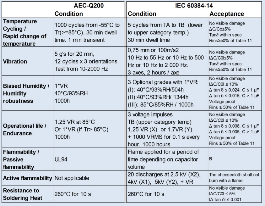
2.1 Acceptance criteria
The first difference is that AEC-Q200 refers to the supplier/user specification, while IEC 60384-14 refers to defined limits. This is not a contradiction as the (capacitor) supplier specification itself typically refers to IEC 60384-14 criteria (or even stricter ones).
In addition, capacitor users must also consider the influence of these specific drifts and limits on their systems.
Examples:
- A 10% drop of capacitance might not be a problem for an AC EMI filter appliance because of its low influence on the cut-off frequency. However, it could provoke a circuit malfunction in other types of appliances that require a stable capacitance value or a balanced voltage (e.g., star connection or capacitive power supply).
- A low insulation resistance value (R) might not be a problem for a single capacitor. But when N capacitors are placed in parallel in the system, this may result in an excess of leakage current for the whole system.
- An increase of the DF dissipation factor (tan ∂) involves an increase in power losses (and self-heating of the capacitor) directly proportional to the square of RMS ripple current IRMS vs. frequency of such a specific system. It may not be an issue at 50/60 Hz with low IRMS, but could provoke an overheating problem with high IRMS and/or frequency.
The limits of Insulation Resistance and the dissipation factor tan ∂ given by IEC 60384-14 have a general approach applying to different capacitor technologies, materials (e.g., ceramic, polypropylene, polyester, paper, etc.) and capacitance ranges. But the reality is that values like dielectric losses, leakage current or temperature coefficient differ between technologies. Therefore, it is necessary to conduct a close check of the capacitor performance that can be applicable to every test as described hereafter.
2.2 Testing
The first point: if that specific test is representative or an acceleration of a real possible condition for the capacitor in the field, the actual parametric drift in that test must be rechecked profoundly to consider the effects of that parametric drift in the real application. For example, a good robustness validation approach is to use pieces of the above mentioned qualification testing (outliers or maximum values) and test them in the real system.
The second point: if the severity of the test itself is so high that it provokes other failure or aging mechanisms different to what actually occurs in the field, the effects of these drifts in real applications should not be considered so exhaustively. In this case, only previous test results shall be relied upon. A good approach is comparing the drifts in the present testing with those in past tests of similar capacitors. Is there clearly a worse behaviour? If so, the questions and possible impacts on the application should be checked very closely.
2.2.1 Temperature Cycling
Five IEC 60384-14 test cycles seem to be clearly insufficient for an automotive application, while a thousand cycles of the AEC-Q200 shock test from -55 °C to 85°C or a maximum category temperature with 1 minute transient, is a well-established accelerated test for capacitors in automotive applications. The severity (transient) seems very high with regard to what could occur in the real application because the mass of the whole system smooths the temperature slopes in these small components. Nevertheless, it is a good approach to evaluate different material behaviour under rapid changes of temperatures compared to historical test data. It is for example useful when testing new materials (case, terminals or dielectrics) or the stress on the contact between dielectric (polymer film) and metals (electrodes and terminals).
The example in figure 1 visualises the test results of a well-established product for automotive applications (TDK series B3267#P, 630 V), which shows only a minor increase in the dissipation factor tan ∂, far below established limits.
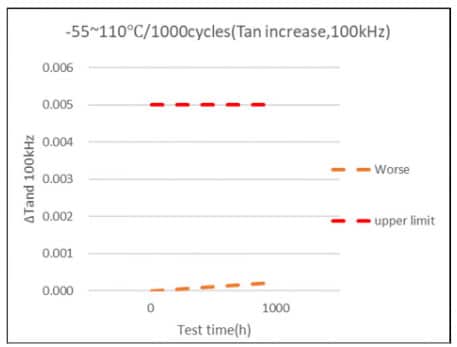
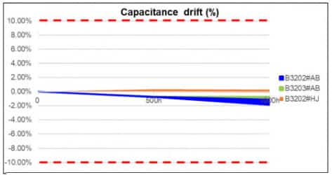
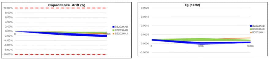
The example in figure 2 compares three TDK Y2 series at -55 °C to 110 °C / 1000 cycles (AEC-Q200), showing a very stable performance for three of them (more stable than those specifically developed for automotive applications: B3203#AB and the latest B3202#H).
2.2.2 Vibration
The vibration test is performed at component level, with a PCB and fixation not necessarily the same as used in the final system. Therefore, it is not representative of what the capacitor may face in field use, but necessary for a basic assurance of performance, e.g., if terminals are robust enough. In this context, the performance is always compared to past results of products already established and proven for automotive applications.
2.2.3 Biased Humidity
AEC-Q200 with 1000 h duration places this test in a midpoint between humidity grade I (504 h) and grade II (1344 h) of IEC 60384-14.
The severity S of any humidity test can be defined as the product of two factors[3] S = ρ * FD, where ρ is the density of water vapor in air, which is a function of both relative humidity and temperature, and FD is the thermal acceleration factor for diffusion.
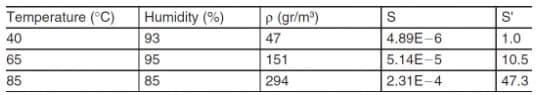
In a real application (with an open) environment, the relative humidity decreases when air temperature increases. Therefore, events like 85 °C/85% RH can only occur in an enclosure with encapsulated humidity (e.g., a test chamber) or for such a short period that diffusion through enclosures will not occur.
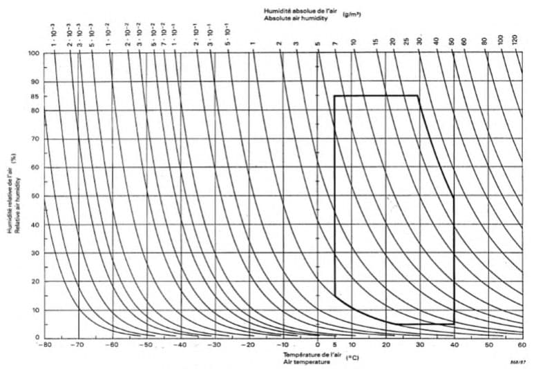
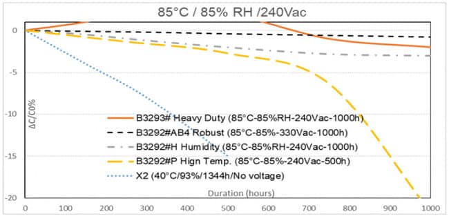
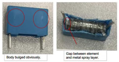
Therefore, while a level of 85 °C/85% RH in a test chamber is valid to evaluate how robust the enclosures are for humidity protection, it provokes much more severe failure modes than in real applications, especially when voltage is applied at the same time, visualised in figure 4 with the performance of the X2 product series from TDK.
Instead, a very common situation in real applications could be an event of 40 °C / 93% RH. In this test case, the parameter drift and its effects must be taken into consideration. When voltage is applied, the probability of partial discharges increases exponentially, more so with an AC voltage than a DC voltage.
So if the intention of this test is to simulate field conditions and a close check to parameter drifts and effects in the application, it is also important to apply an AC or DC waveform as expected in the application as well as to consider average voltages (not accelerated) to not provoke other failure mechanisms.
2.2.4 Operational Life (Endurance)
The endurance test, with acceleration factors of voltage and temperature, is used for the simulation and basic proof of the intended stress in the application. Parameter drifts and their effect in the application should be closely checked.
With a voltage acceleration factor of 1.25 for X capacitors, IEC 60384-14 applies the same approach as AEC-Q200. The voltage acceleration factor of 1.7 for Y capacitors (fig. 5) as per IEC 60384-14 is intended as a safety test (and not a life simulation) due to the criticality of Y class, which is typically connected to ground and therefore to accessible parts, in which case a failure could provoke a severe accident.
Regarding temperature, the main reference for AEC-Q200 film capacitors is 85 °C (or higher, depending on user and supplier), while the IEC 60384-14 approach is the maximum category temperature (typically 105 °C, 110 °C or even 125 °C). Again, IEC 60384-14 is a safety approach (test at worst conditions), while AEC-Q200 focuses on the expected application conditions with some acceleration factor.
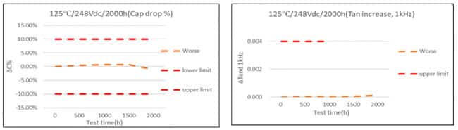
Aging mechanisms of film capacitors will vary with temperature and voltage. Therefore, a too high acceleration of voltage (above a factor of 1.3) in combination with a very high temperature could lead to excessive drifts or breakdowns in testing, which would not be representative of the real application during operation. Figure 6 shows an example of a test at 125 °C with an acceleration factor of 1.1.
2.2.5 Flammability
IEC 60384-14 focuses on component performance in active and passive flammability, while AEC-Q200 focuses on material enclosure class as per UL 94.
- Active flammability involves the application of a high impulse (several kV depending on class) superimposed to AC mains at rated voltage. Failure criterium is the burning of a cheesecloth wrapping around the component.
- Passive flammability exposes the component to a flame and defines a certain time to self-extinguish that flame.
The result is simple: pass or not pass. For this test, parametric drift is not applicable.
2.2.6 Resistance to Soldering Heat
The standard test for resistance to soldering heat at 260 °C and 10 s applies severity conditions and criteria, which are not typically critical for film capacitors, except if its size is very small.
3. xEV Systems: Requirements for EMI Suppression Capacitors
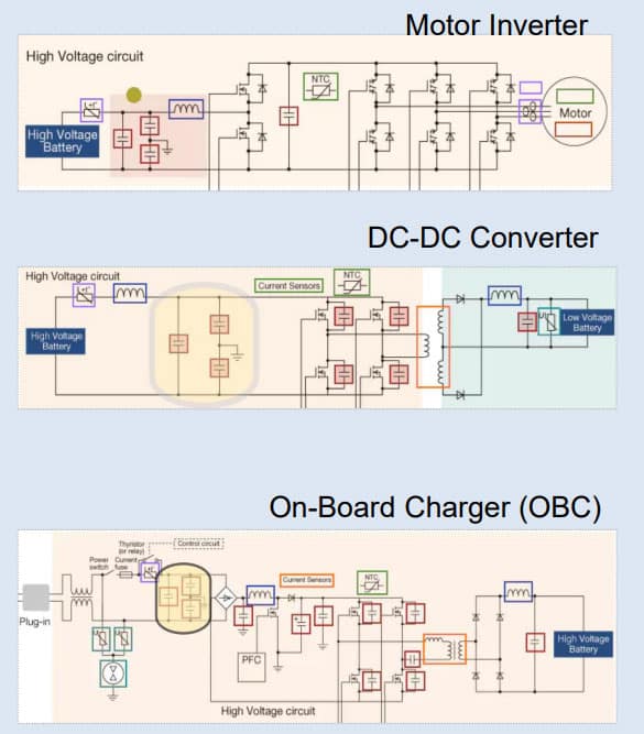
EMI X capacitors (across the lines) and EMI Y capacitors (line to ground) are exemplarily shown in the following block diagrams for three xEV systems: motor inverter (top), DC-DC converter (middle), on-board charger (OBC) (bottom).
The EMI filter area is shadowed, showing the typical circuit position connected to mains and battery power supplies.
3.1 EMI Function and High-Voltage Test
The primary function of EMI capacitors is the filtering of undesired frequency harmonics and also the high-voltage capability for the required safety tests by higher-level standards.
The power supply for the motor inverter and DC-DC converter is the high-voltage battery, and therefore a subsequent DC waveform. Even if it is not an AC waveform as per IEC 60384-14 scope. , this standard shall be considered because of the safety performance required, especially when parts are connected to energy supply lines or ground. IEC 60384-14 edition 4 includes one annex with a description of DC voltage ratings and the qualification testing when required.
The requirements may differ as some users ask for higher voltage tests, for AC testing, for DC testing, for shorter or longer times, for leakage current measurement or even for certain numbers of repetitions with no damage or lifetime decrease.
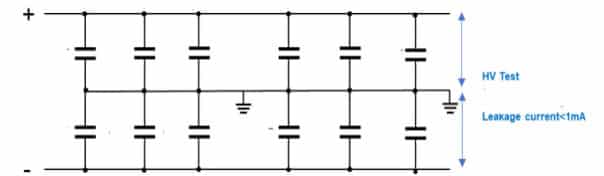
High-voltage AC testing is much more severe for capacitors than DC testing. One of the reasons is that the impedance of a DC power supply is higher. Also, it is more severe because of either higher capacitance values or more capacitors in parallel.
The reason is that in case of self-healings [3] under extreme over-voltages or flashovers in free margins, they are more energetic if the impedance of the whole system under test is lower and therefore vaporizes wider metallization areas.
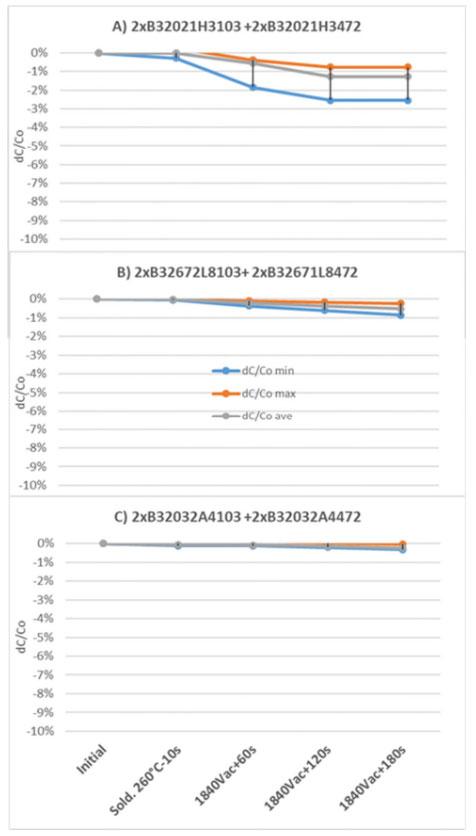
Figure 8. highlights an example of good design practice for high-voltage testing, showing the results of three different product series used in xEV systems as EMI filters connected to ground when submitted to a test level far above specification. The IEC 60384-14 safety test requires 1500 VAC for 60 s.
This real case example of a combined test far above specification and not being included in any standard lets the user decide the proper product depending on high-voltage requirements together with other variables like size, cost or operation.
First part was a soldering heat test to simulate the stress in PCB soldering. Then, an AC high-voltage test was performed for the whole set of capacitance and capacitors (worst case) in the system. Then, by increasing steps of time, possible high-voltage repetitions along the supply chain were emulated. The products B) and C) offered a better performance in this testing, whereas product series A) was eventually selected due to the best combination of size and performance.
All three product series are compliant with AEC-Q200 and pass the high-voltage test required by IEC 60384-14 for Y2 capacitors, including enough margin.
As in the previous and next real example, it is important to include the total capacitance and capacitors of the entire system when submitting it to a high-voltage test. The supplier statement for a single capacitor is important, but it is necessary to consider system level testing.
3.2 Other Stressors
Stressors in table 2, test summary of IEC 60384-14 and AEC-Q200, are mainly voltage, temperature and humidity. But others shall be considered by the user in the selection of the right component for the expected requirements prior to any qualification test.
A good example is the time differential of voltage function dV/dt (V/μs), which may lead to a high peak current (Ipeak) as a result of its product with the capacitance C (μF). If it is exceeded and combined with high voltage or high temperature, it can provoke damage of the internal contact area of the capacitor. Electrical Serial Inductance (ESL) has to be evaluated in case of high dV/dt, as it will provoke an overshoot in voltage affecting other components.
SPICE models with validity in the domain of frequency and time are a useful tool to simulate all of this performance with the whole circuit.
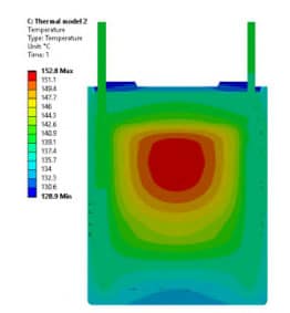
The IRMS (inverter switching frequencies and higher order components) will cause power dissipation and therefore self-heating through the capacitor. That, in combination with high voltage and temperature, can provoke the thermal avalanche of the capacitor.
This assessment for thermal behaviour is not included in any testing of the mentioned international standards, but TDK offers support and also tools and spice models to perform the simulation of certain application conditions, e.g., CLARA (Capacitor Life and Rating App) for film capacitors.
4. TDK Film Capacitors for xEV
TDK datasheets offer a comprehensive combination of the relevant applicable IEC standard together with the AEC-Q200 compliance. Tests and limits are well described and fully available for the users of the capacitors. TDK offers simulation tools (CLARA, Capacitor Life And Rating Application) and complex SPICE models valid in the domains of time and frequency to support the selection of the right capacitor for every application, thereby preventing over-design or under-design. Everything can be found on the website.
The reference standard requirements combined with the most diverse application requirements are a constant challenge for the capacitor manufacturer, resulting in continuous new series developments and market launches.
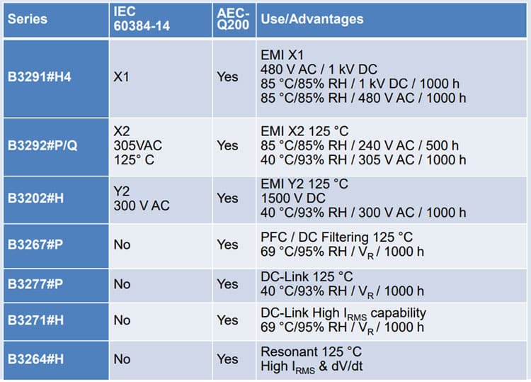
The following table highlights the latest TDK product series, which are used in xEV systems. Some of them do not have the IEC 60384-14 certification, but comply with the required safety level and performance by the user.
5. Reference
[1] IEC 60384-14 Edition 4.0, “Fixed capacitors for electromagnetic interference suppression and connection to the supply mains”, 2013-06, AMD1:2016
[2] AEC-Q200 REV D, stress test qualification for passive components, Automotive Electronics Council, 2010
[3] Data Book Film Capacitors, TDK, 2018
[4] IEC 721-3-3 Second edition, classification of environmental conditions, 1994
Acknowledgement
The authors thank the International Electrotechnical Commission (IEC) for permission to reproduce information from its International Standards. All such extracts are copyright of IEC, Geneva, Switzerland. All rights reserved. Further information on the IEC is available from www.iec.ch.
IEC has no responsibility for the placement and context in which the extracts and contents are reproduced by the author, nor is IEC in any way responsible for the other content or accuracy there.


