Passive Components Blog
No Result
View All Result
  • Home
  • NewsFilter
    • All
    • Aerospace & Defence
    • Antenna
    • Applications
    • Automotive
    • Capacitors
    • Circuit Protection Devices
    • electro-mechanical news
    • Filters
    • Fuses
    • Inductors
    • Industrial
    • Integrated Passives
    • inter-connect news
    • Market & Supply Chain
    • Market Insights
    • Medical
    • Modelling and Simulation
    • New Materials & Supply
    • New Technologies
    • Non-linear Passives
    • Oscillators
    • Passive Sensors News
    • Resistors
    • RF & Microwave
    • Telecommunication
    • Weekly Digest

    Thermal Modeling of Magnetics

    ESA SPCD 26 Call for Papers Extended to 30th March

    Wk 11 Electronics Supply Chain Digest

    Binder Extends NCC Circular Connectors for Harsh Environments

    Standard vs Planar LLC transformers Comparison for Battery Chargers

    Würth Elektronik and Grinn Launch Edge AI Cooperation

    Bourns Expanded Semi-Shielded Low Profile Automotive Power Inductor

    Peak Nano to Develop Fusion Grade High Energy Film Capacitors

    Murata New Vibration Sensor Targets High‑Frequency Predictive Maintenance

    Trending Tags

    • Ripple Current
    • RF
    • Leakage Current
    • Tantalum vs Ceramic
    • Snubber
    • Low ESR
    • Feedthrough
    • Derating
    • Dielectric Constant
    • New Products
    • Market Reports
  • VideoFilter
    • All
    • Antenna videos
    • Capacitor videos
    • Circuit Protection Video
    • Filter videos
    • Fuse videos
    • Inductor videos
    • Inter-Connect Video
    • Non-linear passives videos
    • Oscillator videos
    • Passive sensors videos
    • Resistor videos

    Thermal Modeling of Magnetics

    Standard vs Planar LLC transformers Comparison for Battery Chargers

    How Modern Tools Model Magnetic Components for Power Electronics

    Advanced Loss Modeling for Planar Magnetics in the Frenetic Planar Tool

    2026 Power Magnetics Design Trends: Flyback, DAB and Planar

    Enabling Software‑Defined Vehicle Architectures: Automotive Ethernet and Zonal Smart Power

    Calculating Resistance Value of a Flyback RC Snubber 

    One‑Pulse Characterization of Nonlinear Power Inductors

    Thermistor Linearization Challenges

    Trending Tags

    • Capacitors explained
    • Inductors explained
    • Resistors explained
    • Filters explained
    • Application Video Guidelines
    • EMC
    • New Products
    • Ripple Current
    • Simulation
    • Tantalum vs Ceramic
  • Knowledge Blog
  • DossiersNew
  • Suppliers
    • Who is Who
  • PCNS
    • PCNS 2025
    • PCNS 2023
    • PCNS 2021
    • PCNS 2019
    • PCNS 2017
  • Events
No Result
View All Result
Passive Components Blog
No Result
View All Result

Capacitech C-Link Supercapacitors for AI Data Center Voltage Spikes Mitigation

23.2.2026
Reading Time: 8 mins read
A A

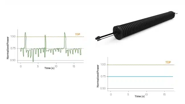
AI data centers are pushing power infrastructures to their limits, with ultra‑fast load steps from GPU clusters causing severe voltage sags and nuisance trips. Supercapacitor‑based systems such as Capacitech’s C‑Link modules add a fast, high‑power buffer that stabilizes the DC bus during these transients. This enables operators to increase rack power density and AI utilization without massive over‑provisioning of batteries, UPS systems, or grid capacity.

Why AI data centers struggle with voltage sags

AI and accelerated compute workloads create highly dynamic, spiky power demand rather than smooth, predictable profiles. GPU clusters can step from idle to several kilowatts per server in milliseconds, driving abrupt current increases along the entire power chain.

RelatedPosts

Cable Supercapacitors in Microgrids and Renewable Applications

Capacitech PowerLink: High Power Cable Supercapacitor Energy Storage for Space Constrained Applications

Supercapacitor Cables Enable Better Batteries

These rapid load steps can lead to:

  • Voltage sags on distribution buses when power electronics and upstream sources cannot ramp fast enough
  • Nuisance tripping of breakers and protection devices due to transient overcurrent and inrush events
  • Stress and premature aging of PSUs and UPS systems operated far from their optimum efficiency region
  • Unexpected server resets or errors when supply rails drop below allowable limits, even for a few milliseconds

Traditional battery‑based backup solutions are optimized for energy, not instantaneous power, and often react too slowly to fully catch microsecond‑to‑millisecond events. Supercapacitors fill this gap by delivering very high current on short timescales, effectively bridging between the fast transient and the slower response of UPS, generators, and the grid.

Key features and benefits of C‑Link supercapacitor modules

Capacitech’s C‑Link solution is a modular supercapacitor‑based energy storage system designed as a power‑quality layer for data centers. It focuses on high power handling and millisecond‑class response rather than long‑duration backup.

Key characteristics include:

  • Millisecond response time to voltage sags and transient events on data center buses
  • High power density for large, short‑duration current pulses during AI workload spikes
  • Modular architecture that can be scaled with rack count, power density, or AI adoption levels
  • Flexible physical deployment on walls, fences, or cable trays, preserving valuable white‑space and rack area
  • Integration as an add‑on layer in existing power architectures, minimizing need for civil works or major retrofit construction

From an operator’s perspective, the main benefits are:

  • Stabilized bus voltage during AI load spikes, reducing server glitches and downtime risk
  • Less need to oversize UPS or battery systems purely for peak power rather than energy autonomy
  • Improved utilization of existing infrastructure by smoothing the instantaneous power profile seen by the grid connection and backup systems
  • Faster deployment (described as months rather than years) compared to large‑scale infrastructure reinforcement according to the manufacturer’s material
FeatureC‑Link ModulesBatteries (Li‑Ion, LTO)Supercapacitor OEMsFlywheels
Response TimeMillisecondsSeconds to minutesMillisecondsMilliseconds to seconds
Installation TimeDaysMonthsWeeks to monthsWeeks
Installation RequirementsTraditional, wall, fence, cable trays; single technicianCabinets, concrete pads, cranes, heavy equipmentCabinets, concrete pads, cranes, heavy equipmentHeavy foundation, specialized installation
Permitting ComplexityMinimalExtensive (lithium safety)Minimal to moderateComplex
Operational Life10–20 years5–10 years10–20 years10–20 years
MaintenanceMinimalModerate to highMinimalHigh
ScalabilityAdd/relocate modulesLimitedLimitedLimited
Cost per kWLowHigh (oversized)Low to moderateHigh
Best Use CaseMillisecond surges, high powerLong discharge cyclesMillisecond surges, high powerMedium duration
Space EfficiencyModular, flexible placementCabinet and container basedCabinet and container basedLarge footprint

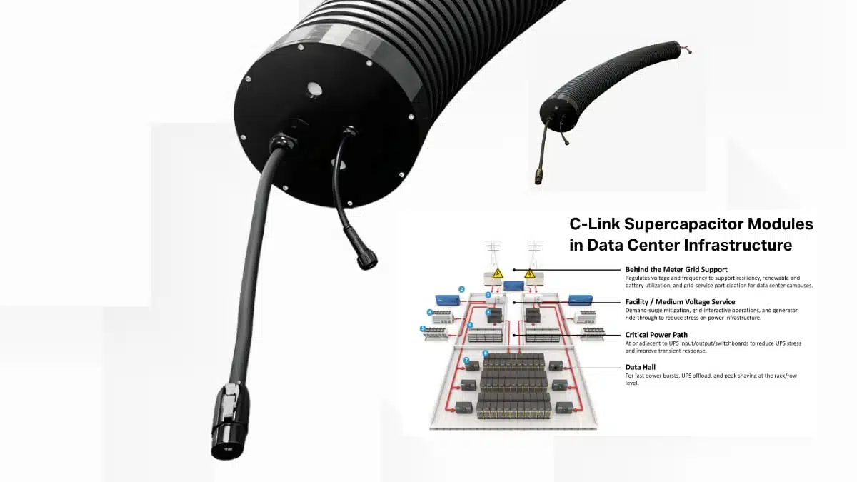
Typical applications in data center power paths

Supercapacitor modules like C‑Link fit best where transient power events are most harmful but durations remain short. In AI data centers, this typically aligns with high‑power but brief GPU load surges and simultaneous rack startup sequences.

Representative use cases include:

  • AI‑focused racks with dense GPU configurations that exhibit steep load ramps and frequent workload‑driven spikes
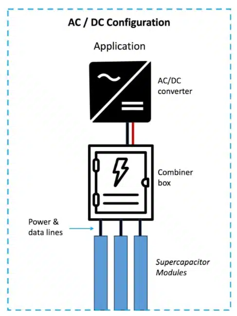
  • DC bus stabilization at intermediate distribution levels (for example 380 V or 48 V DC segments) to buffer transient currents
  • Support for UPS systems by offloading the most aggressive power spikes, allowing batteries to handle longer events
  • Protection of switchgear and power distribution units against current spikes that would otherwise cause nuisance tripping
  • Retrofit upgrades in existing facilities where grid capacity or UPS scaling is constrained, but AI demand is increasing

Because the modules handle very short‑term events, they are not a replacement for traditional UPS or generator backup. Instead, they complement those systems by providing a high‑speed “shock absorber” in front of them.

Design‑in notes for engineers

From a design engineer’s standpoint, integrating supercapacitor modules into a data center requires coordinating electrical, mechanical, and operational aspects. The C‑Link concept addresses these areas but still needs project‑specific engineering.

C-Link installation location. Typical AC connection is 480VAC.

Consider the following points during design‑in:

  • Define the transient profile
    Characterize worst‑case load steps from AI workloads: magnitude, rise time, duration, and repetition. This determines the required supercapacitor power and energy, as well as allowable voltage droop on the bus.
  • Select the right system level
    Decide whether C‑Link should sit at a central DC bus, per‑row distribution, or closer to rack‑level distribution. Central placement simplifies implementation but may reduce effectiveness for very localized, high‑frequency events.
  • Coordinate with UPS and protection
    Ensure the supercapacitor system and UPS control strategies are aligned so that the modules absorb short‑term sags, while UPS and generators handle longer events. Protective device settings (breakers, relays) should be reviewed to avoid unintended interactions under high di/dt conditions.
  • Mechanical and thermal integration
    Take advantage of the flexible mounting options (walls, cable trays, fences) to keep IT floor space free. Verify clearances, cable lengths, and thermal environment so that the modules operate within their specified temperature and ventilation limits.
  • Monitoring and maintenance
    Supercapacitor systems typically require less maintenance than batteries, but their health should still be integrated into facility monitoring. Check which monitoring interfaces (for example SNMP, Modbus, REST APIs) are available from the C‑Link system and plan alarm strategies accordingly.
  • Lifecycle and TCO considerations
    Because supercapacitors can withstand a very high number of cycles, they are particularly suitable for constant AI load smoothing. When performing a total cost of ownership analysis, consider reduced battery cycling, fewer nuisance outages, and deferred grid or UPS upgrades alongside the direct system cost.

For detailed electrical connection diagrams, busbar sizing rules, and protection coordination, Capacitech instructs users to rely on project documentation and datasheets rather than generic rules of thumb.

Source

This article is based on information published by Capacitech Energy about its C‑Link supercapacitor modules for AI and data center applications, supplemented by general industry material on supercapacitors in data centers. All detailed ratings and configuration options should be confirmed against the latest manufacturer datasheets and project documentation.

References

  1. Capacitech Energy – How Supercapacitors Eliminate Voltage Sags in AI Data Centers
  2. Capacitech Energy – C‑Link Supercapacitor Module Product Overview
  3. Capacitech Energy – Blog | Supercapacitor Insights

Related

Recent Posts

ESA SPCD 26 Call for Papers Extended to 30th March

16.3.2026
73

Binder Extends NCC Circular Connectors for Harsh Environments

13.3.2026
2

Standard vs Planar LLC transformers Comparison for Battery Chargers

13.3.2026
15

Bourns Expanded Semi-Shielded Low Profile Automotive Power Inductor

12.3.2026
14

Peak Nano to Develop Fusion Grade High Energy Film Capacitors

11.3.2026
29

Murata New Vibration Sensor Targets High‑Frequency Predictive Maintenance

10.3.2026
24

Panasonic Expands Automotive PP Film Capacitors Voltage Range

9.3.2026
23

Panasonic Extends Automotive Power Inductor Line

9.3.2026
30

February 2026 Interconnect, Passives and Electromechanical Components Market Insights

9.3.2026
57

Upcoming Events

Mar 19
13:00 - 14:00 CDT

Smart Consideration of Inductor Thermal Performance

Mar 21
All day

PSMA Capacitor Workshop 2026

Apr 21
16:00 - 17:00 CEST

Heatsink Solutions: Thermal Management in electronic devices

View Calendar

Popular Posts

  • Buck Converter Design and Calculation

    0 shares
    Share 0 Tweet 0
  • Boost Converter Design and Calculation

    0 shares
    Share 0 Tweet 0
  • Flyback Converter Design and Calculation

    0 shares
    Share 0 Tweet 0
  • LLC Resonant Converter Design and Calculation

    0 shares
    Share 0 Tweet 0
  • MLCC Manufacturers Consider Price Increase as AI Demand Outpaces Supply

    0 shares
    Share 0 Tweet 0
  • Dual Active Bridge (DAB) Topology

    0 shares
    Share 0 Tweet 0
  • Ripple Current and its Effects on the Performance of Capacitors

    3 shares
    Share 3 Tweet 0
  • MLCC and Ceramic Capacitors

    0 shares
    Share 0 Tweet 0
  • MLCC Case Sizes Standards Explained

    0 shares
    Share 0 Tweet 0
  • 3-Phase EMI Filter Design, Simulation, Calculation and Test

    0 shares
    Share 0 Tweet 0

Newsletter Subscription


Passive Components Blog

© EPCI - Leading Passive Components Educational and Information Site

  • Home
  • Privacy Policy
  • EPCI Membership & Advertisement
  • About

No Result
View All Result
  • Home
  • Knowledge Blog
  • PCNS

© EPCI - Leading Passive Components Educational and Information Site

This website uses cookies. By continuing to use this website you are giving consent to cookies being used. Visit our Privacy and Cookie Policy.
Go to mobile version