Passive Components Blog
No Result
View All Result
  • Home
  • NewsFilter
    • All
    • Aerospace & Defence
    • Antenna
    • Applications
    • Automotive
    • Capacitors
    • Circuit Protection Devices
    • electro-mechanical news
    • Filters
    • Fuses
    • Inductors
    • Industrial
    • Integrated Passives
    • inter-connect news
    • Market & Supply Chain
    • Market Insights
    • Medical
    • Modelling and Simulation
    • New Materials & Supply
    • New Technologies
    • Non-linear Passives
    • Oscillators
    • Passive Sensors News
    • Resistors
    • RF & Microwave
    • Telecommunication
    • Weekly Digest

    Smolteks CNF MIM Capacitor Break 1 µF/mm²

    Samsung Electro-Mechanics Releases 0201 X7T 1uF 6.3V MLCC for ADAS Applications

    Murata Announces 0402 Automotive Chip Ferrite Beads for V2X

    2025 Thick and Thin Film Resistor Networks Environment Overview

    Role of High-Q Ceramic Filters to Overcome GNSS Jamming

    Optimization of IoT for GEO NB-NTN Hybrid Connectivity

    TDK Releases Automotive Power-Over-Coax Inductor for Filters

    Advanced Conversion Announces Mass Production of 200C Film Capacitors

    VinaTech Supercapacitors: Enhancing Smart Meter Reliability and Efficiency

    Trending Tags

    • Ripple Current
    • RF
    • Leakage Current
    • Tantalum vs Ceramic
    • Snubber
    • Low ESR
    • Feedthrough
    • Derating
    • Dielectric Constant
    • New Products
    • Market Reports
  • VideoFilter
    • All
    • Antenna videos
    • Capacitor videos
    • Circuit Protection Video
    • Filter videos
    • Fuse videos
    • Inductor videos
    • Inter-Connect Video
    • Non-linear passives videos
    • Oscillator videos
    • Passive sensors videos
    • Resistor videos

    Understanding Switched Capacitor Converters

    Coupled Inductors Circuit Model and Examples of its Applications

    Inductor Resonances and its Impact to EMI

    Highly Reliable Flex Rigid PCBs, Würth Elektronik Webinar

    Causes of Oscillations in Flyback Converters

    How to design a 60W Flyback Transformer

    Modeling and Simulation of Leakage Inductance

    Power Inductor Considerations for AI High Power Computing – Vishay Video

    Coupled Inductors in Multiphase Boost Converters

    Trending Tags

    • Capacitors explained
    • Inductors explained
    • Resistors explained
    • Filters explained
    • Application Video Guidelines
    • EMC
    • New Products
    • Ripple Current
    • Simulation
    • Tantalum vs Ceramic
  • Knowledge Blog
  • Suppliers
    • Who is Who
  • Events
No Result
View All Result
Passive Components Blog
No Result
View All Result

Ceramic Coaxial Resonator Filters Basics

4.1.2023
Reading Time: 4 mins read
A A

This blog article from Knowles Precision Devices perform a deep dive on ceramic coaxial resonator filters basics, its construction, function and features.

Before jumping into a discussion on ceramic coaxial resonators, it is important to understand what a resonator is and how these electrical components work.

RelatedPosts

Role of High-Q Ceramic Filters to Overcome GNSS Jamming

Knowles Extends Range and Performance of C0G MLCC Capacitors

Supercapacitors Benefits in Industrial Valve Fail-Safe Control Systems

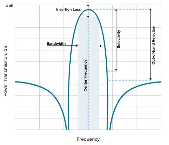
In general, a resonator is an essential component for constructing a bandpass filter since the resonator is what will allow specified frequencies, or bands of frequencies, to pass through the filter as shown in Figure 1.

A simple resonator, such as an LC resonator, can store frequency-dependent electric energy in the capacitance (C) and magnetic energy in the inductance (L).The resonant frequency of a resonator occurs when the energy stored in electric field is equal to the energy stored in the magnetic field.

Figure 1. An illustration of a band pass filter and its key characteristics.
Figure 2. An example showing how electrical and magnetic energy travel in a coaxial transmission line.

An Overview of Ceramic Coaxial Resonators

Now that we’ve established the basics of how a resonator works, we can explore how a ceramic coaxial resonator functions. In general, a ceramic coaxial resonator is a transmission line resonator that operates in transverse electromagnetic (TEM) mode.

Figure 3. A depiction of how a signal will be impacted depending on the type of ceramic coaxial resonator added.

TEM mode has both E- and H-field components at right angles to the z-direction and no signals in the direction of propagation as shown in Figure 2.

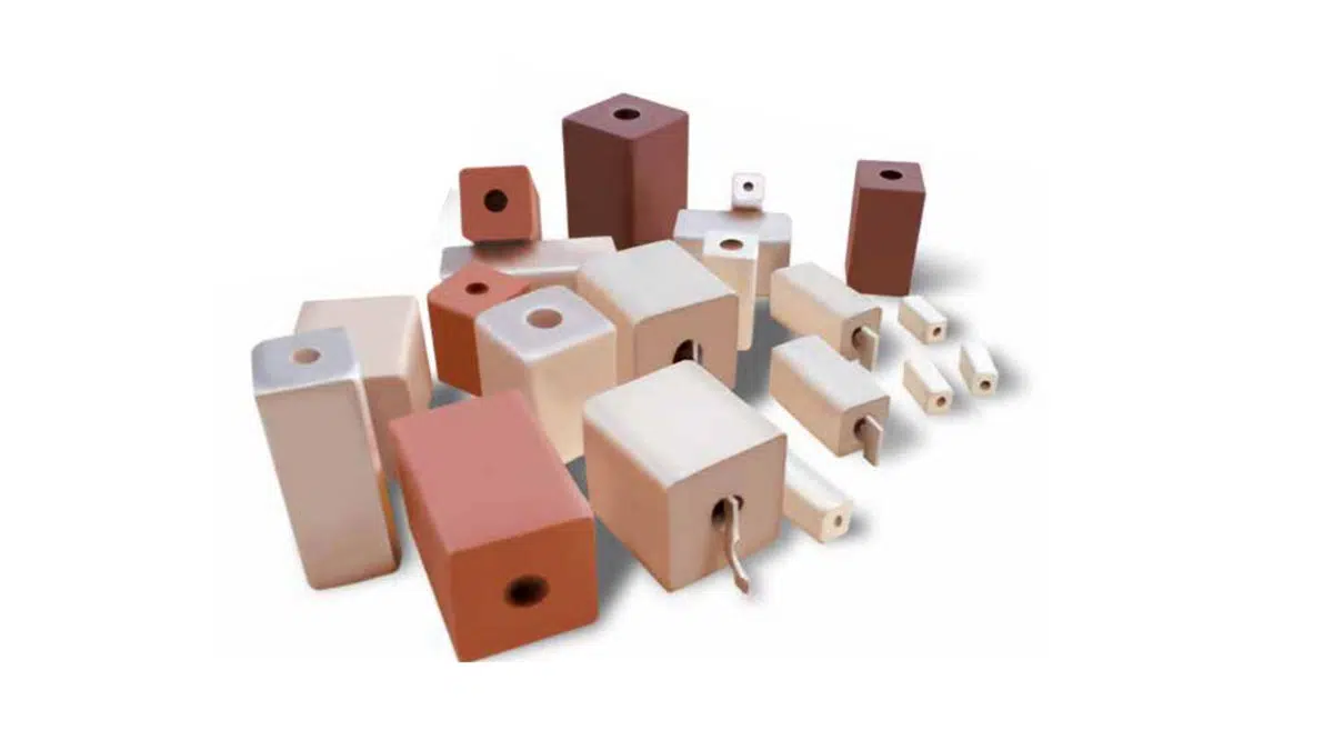
A coaxial resonator line is usually configured using a ceramic rectangular prism with a coaxial hole running through the center. The dielectric type, length, and metallization will dictate performance at frequency.

The line can also be cut to a specific length related to the wavelength of the frequency of interest. For example, to make the lines shorter we can use ceramics with specific dielectric constants, which will shrink the wavelength of the frequency we are interested in.

Figure 3 shows an example of how a signal is impacted when either a λ/4 resonator with one end metallized or a λ/2 resonator with both ends open is added.

Using Ceramic Coaxial Resonators to Make Filters

Let’s now look at when it may be advantageous to use ceramic coaxial resonators to create filters. In previous blog post, Basic Filter Circuits Explained, we showed a number of examples of how you can construct simple filters from different combinations of resistors (Rs), Cs, and Ls. While this approach is great for developing simple filters, as operating frequencies increase and filtering needs become more complex, you are likely to run into a variety of issues with performance and size if you continue to try to use only these basic circuit building blocks.

Instead, short-circuit ceramic coaxial resonators made with modern high-performance ceramic dielectric materials can be used in place of LC resonators. The high Q possible in the UHF and microwave frequency range makes ceramic coaxial resonators an ideal option for many applications, especially when cost, size, and stability are important.

The Capabilities of Ceramic Coaxial Resonator Filters

The plot in Figure 4 shows typical filter bandwidth vs frequency on multiple filter types including ceramic coaxial filters made by Knowles Precision Devices.

Figure 4. Bandwidth vs frequency range of different filter technology with ceramic coaxial resonator filters dark blue area with a yellow outline.

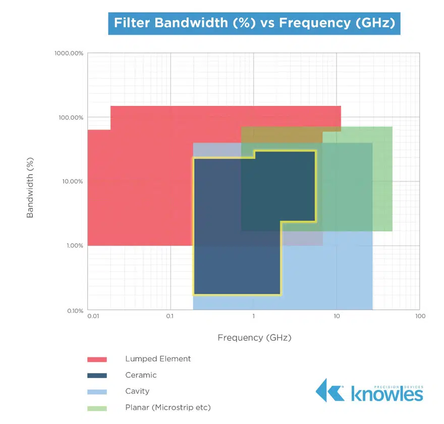
Typical ceramic coaxial resonator filters can be found to cover the following ranges:

  • Narrow to moderate bandwidths for F0 = 200MHz to 2.2 GHz for large profile 12 mm and 18 mm resonator bandpass filters, 0.2 percent to 30 percent fractional bandwidth.
  • Moderate to wide bandwidths for F0 = 1 GHz to 6 GHz for small profile 2 mm to 6 mm resonator bandpass filters, 3 percent to 45 percent fractional bandwidth
  • Narrow bandwidth band reject filters for F0 = 400 MHz to 4 GHz, 1 percent to 15 percent fractional bandwidth

Related

Source: Knowles

Recent Posts

Role of High-Q Ceramic Filters to Overcome GNSS Jamming

19.6.2025
14

Bourns Introduces 1206 Multilayer Common Mode Filters

16.6.2025
9

Smoltek CNF-MIM Capacitor Commercialization Update

11.6.2025
31

Understanding Switched Capacitor Converters

9.6.2025
75

What Track Width To Use When Routing PCB

6.6.2025
32

Capacitance Definition of Non-Linear Voltage Dependent Capacitors

5.6.2025
34

Bourns Releases New SMD Line Filter for Enhanced EMI Suppression

4.6.2025
16

TDK Expands 3-terminal Automotive SMD Chip Filters to 35V

4.6.2025
21

Coupled Inductors Circuit Model and Examples of its Applications

21.5.2025
137

Würth Elektronik Introduces LTspice Models for ESD Products

21.5.2025
68

Upcoming Events

Jun 24
16:00 - 17:00 CEST

Limitations of PSFB converters and improvements by a variable inductor ft. Sam Ben-Yaakov

Jun 24
17:00 - 18:00 CEST

Ultra-Compact and Efficient Switched-Capacitor Power Converters

Jul 23
13:00 - 14:00 CEST

PCB design for a Smartwatch

View Calendar

Popular Posts

  • Buck Converter Design and Calculation

    0 shares
    Share 0 Tweet 0
  • Boost Converter Design and Calculation

    0 shares
    Share 0 Tweet 0
  • Flyback Converter Design and Calculation

    0 shares
    Share 0 Tweet 0
  • What is a Dielectric Constant and DF of Plastic Materials?

    4 shares
    Share 4 Tweet 0
  • LLC Resonant Converter Design and Calculation

    0 shares
    Share 0 Tweet 0
  • Ripple Current and its Effects on the Performance of Capacitors

    3 shares
    Share 3 Tweet 0
  • How to Design an Inductor

    0 shares
    Share 0 Tweet 0
  • SEPIC Converter Design and Calculation

    0 shares
    Share 0 Tweet 0
  • Dual Active Bridge (DAB) Topology Explained

    0 shares
    Share 0 Tweet 0
  • Why Low ESR Matters in Capacitor Design

    0 shares
    Share 0 Tweet 0

Newsletter Subscription


Passive Components Blog

© EPCI - Leading Passive Components Educational and Information Site

  • Home
  • Privacy Policy
  • EPCI Membership & Advertisement
  • About

No Result
View All Result
  • Home
  • Knowledge Blog
  • Premium Suppliers

© EPCI - Leading Passive Components Educational and Information Site

This website uses cookies. By continuing to use this website you are giving consent to cookies being used. Visit our Privacy and Cookie Policy.
Go to mobile version