Passive Components Blog
No Result
View All Result
  • Home
  • NewsFilter
    • All
    • Aerospace & Defence
    • Antenna
    • Applications
    • Automotive
    • Capacitors
    • Circuit Protection Devices
    • electro-mechanical news
    • Filters
    • Fuses
    • Inductors
    • Industrial
    • Integrated Passives
    • inter-connect news
    • Market & Supply Chain
    • Market Insights
    • Medical
    • Modelling and Simulation
    • New Materials & Supply
    • New Technologies
    • Non-linear Passives
    • Oscillators
    • Passive Sensors News
    • Resistors
    • RF & Microwave
    • Telecommunication
    • Weekly Digest

    Common Mistakes in Flyback Transformer Specs

    Vishay Releases Miniature SMD Trimmers for Harsh Environments

    Würth Elektronik Releases Push-Button and Main Switches

    Littelfuse Unveils High-Precision TMR Angle Magnetic Sensors

    Stackpole Extends Voltage of High Temp Chip Resistors

    High Voltage MLCCs Meeting the Growing Demand for Efficiency in Power Conversion

    Bourns Releases High Power High Ripple Chokes

    KYOCERA AVX Releases Hermaphroditic WTW and WTB Connectors

    Radiation Tolerance of Tantalum and Ceramic Capacitors

    Trending Tags

    • Ripple Current
    • RF
    • Leakage Current
    • Tantalum vs Ceramic
    • Snubber
    • Low ESR
    • Feedthrough
    • Derating
    • Dielectric Constant
    • New Products
    • Market Reports
  • VideoFilter
    • All
    • Antenna videos
    • Capacitor videos
    • Circuit Protection Video
    • Filter videos
    • Fuse videos
    • Inductor videos
    • Inter-Connect Video
    • Non-linear passives videos
    • Oscillator videos
    • Passive sensors videos
    • Resistor videos

    Percolation Phenomenon and Reliability of Molded Power Inductors in DC/DC converters

    Root Causes and Effects of DC Bias and AC in Ceramic Capacitors

    How to Calculate the Output Capacitor for a Switching Power Supply

    Switched Capacitor Converter Explained

    Understanding Inductor Dot Markings and Their Application in LTspice

    Accelerating Full Bridge LLC Resonant Converter Design with Frenetic AI

    Understanding Switched Capacitor Converters

    Coupled Inductors Circuit Model and Examples of its Applications

    Inductor Resonances and its Impact to EMI

    Trending Tags

    • Capacitors explained
    • Inductors explained
    • Resistors explained
    • Filters explained
    • Application Video Guidelines
    • EMC
    • New Products
    • Ripple Current
    • Simulation
    • Tantalum vs Ceramic
  • Knowledge Blog
  • Suppliers
    • Who is Who
  • Events
No Result
View All Result
Passive Components Blog
No Result
View All Result

Contact Force and Mating Mechanics

8.9.2021
Reading Time: 2 mins read
A A

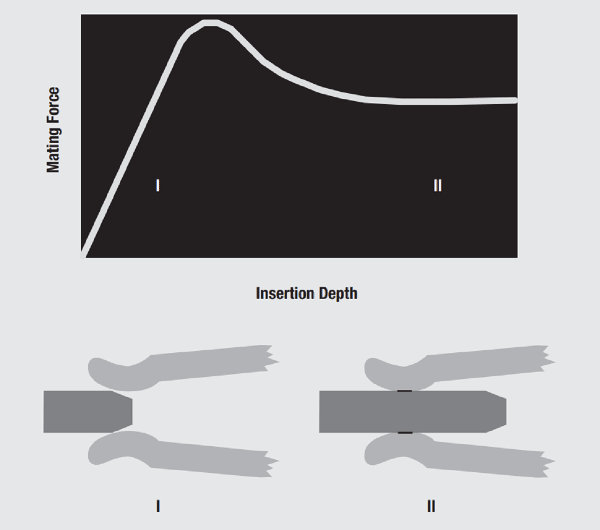
Consider now the effects of contact force on the mating mechanics of a connector. Figure 2.20 schematically illustrates the mating, or insertion, force of a pin as a function of the insertion depth of the pin into the receptacle contact. The receptacle is the spring contact in this system.

Fig. 2.20: Mating force as function of insertion depth

There are two phases to the insertion force. In phase I the receptacle contact beams are being deflected by the pin and in phase II the beams are fully deflected and the receptacle contact is sliding along the surface of the pin contact. The insertion force in phase II is simply the product of the coefficient of friction, and the contact force because the friction force acts in opposition to the insertion force.

RelatedPosts

Polymer Materials and Processing

What is RF Connector

Connector Materials and Processes

The insertion force in phase I arises from two contributions, the displacement of the receptacle contact beams by the pin and the friction forces created as the pin slides against the receptacle. The contact force and the insertion force increase as the beam is deflected dependent on the stiffness, or spring rate of the receptacle contact. The friction forces are always opposed to the direction of insertion and perpendicular to the tangent of the pin surface at the point of contact with the receptacle beam. Thus the friction force contribution varies in direction as the receptacle contact slides up the contour of the pin contact. These variations are responsible for the magnitude and width of the peak in the insertion force curve.

Fig. 2.21: Insertion force

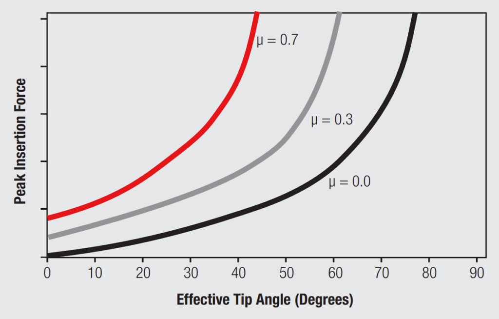
Figure 2.21 illustrates the variation in peak insertion force as a function of the coefficient of friction, μ. The peak insertion force is the minimum mating force for the contact system. The contact force is a dominant contributor to the mating force and the same concern about a discontinuous change in friction coefficient, analogous to the wear coefficient discussed previously, applies. The values of μ shown are for an ideal frictionless case, μ = 0 and for nominal coefficients friction for gold, μ = 0.3 and tin, μ = 0.7. The abscissa shows the effective tip angle, the angle between the tangents to the pin and socket surfaces at the point of contact. Small effective tip angles will have a low and wide peak and the height will increase and the width decrease as the effective tip angle increases.

Related

Source: Wurth elektronik

Recent Posts

Non-Magnetic Interconnects

23.4.2025
25

10 Tips for Ensuring Reliability of Discrete Wire Assemblies

20.2.2025
55

Polymer Materials and Processing

11.8.2025
47

Basic PCB Technology Overview

1.7.2025
17

What is RF Connector

17.12.2024
9

Creepage and Clearance of Connector

25.7.2025
17

Microwave Multi Line Connectors Mounting and Handling Precautions

11.8.2025
3

BASIC PCB Design Rules – Layout

1.7.2025
29

MEMR RF Relay for Space Compact Redundancy Ring

17.12.2024
3

Connector Temperature Rise and Derating

13.1.2023
25

Upcoming Events

Aug 27
17:00 - 18:00 CEST

Capacitor Assemblies for High-Power Circuit Designs

Sep 3
15:30 - 17:30 CEST

How to Choose Your Magnetic Supplier

Sep 22
September 22 @ 13:00 - September 25 @ 15:15 EDT

Pre Cap Visual Inspection per Mil-Std-883 (TM 2017)

Sep 30
September 30 @ 12:00 - October 2 @ 14:00 EDT

MIL-Std-883 TM 2010

Oct 17
12:00 - 14:00 EDT

External Visual Inspection per MIL-STD-883 TM 2009

View Calendar

Popular Posts

  • Buck Converter Design and Calculation

    0 shares
    Share 0 Tweet 0
  • Boost Converter Design and Calculation

    0 shares
    Share 0 Tweet 0
  • Flyback Converter Design and Calculation

    0 shares
    Share 0 Tweet 0
  • LLC Resonant Converter Design and Calculation

    0 shares
    Share 0 Tweet 0
  • What is a Dielectric Constant and DF of Plastic Materials?

    4 shares
    Share 4 Tweet 0
  • Ripple Current and its Effects on the Performance of Capacitors

    3 shares
    Share 3 Tweet 0
  • Dual Active Bridge (DAB) Topology Explained

    0 shares
    Share 0 Tweet 0
  • How to Design an Inductor

    0 shares
    Share 0 Tweet 0
  • MLCC Case Sizes Standards Explained

    0 shares
    Share 0 Tweet 0
  • MLCC and Ceramic Capacitors

    0 shares
    Share 0 Tweet 0

Newsletter Subscription


Passive Components Blog

© EPCI - Leading Passive Components Educational and Information Site

  • Home
  • Privacy Policy
  • EPCI Membership & Advertisement
  • About

No Result
View All Result
  • Home
  • Knowledge Blog
  • Premium Suppliers

© EPCI - Leading Passive Components Educational and Information Site

This website uses cookies. By continuing to use this website you are giving consent to cookies being used. Visit our Privacy and Cookie Policy.
Go to mobile version