Choosing the right RF connector isn’t just about what fits — it directly impacts signal integrity, frequency performance, and long-term reliability.
RF connectors are more than just mechanical mating parts on a coaxial cable – they define how reliably high‑frequency signals move between boards, cables, and modules. The choice of connector influences insertion loss, VSWR, frequency ceiling, power handling, and long‑term reliability, especially in harsh environments.
This article overviews the most commonly used RF coaxial connector families, shows their typical frequency and power capabilities, and provides practical guidance on selection for test, communication, and infrastructure applications.
Key Parameters When Selecting RF Connectors
Before diving into specific types, it is useful to frame RF connectors in terms of a few core electrical and mechanical characteristics.cdebyte+1
- Characteristic impedance
Most RF connectors are standardized at 50 Ω for RF and microwave systems or 75 Ω for broadcast, video and some telecom infrastructure. Mixing impedances (for example, 50 Ω connector on a 75 Ω cable) introduces discontinuities that cause reflections and increased VSWR. - Frequency range
Connector geometry, dielectric, and tolerances define the usable frequency range; miniature families like SMA, MCX and SMP reach into tens of GHz, whereas legacy types such as UHF are effectively limited to the low hundreds of MHz.f1chf. - Power handling
Larger bodies with better heat dissipation and higher breakdown voltages (for example, N and 7/16 DIN) can carry significantly higher RF power than small laboratory connectors. Power capability typically falls as frequency increases due to skin effect and dielectric losses. - Coupling mechanism
Bayonet, threaded and push‑on interfaces trade off connection speed versus robustness and repeatability, which becomes critical in field installations or high‑vibration environments. - Physical size and ruggedness
Compact connectors like MCX/MMCX are optimised for dense layouts and portable devices, while larger N and 7/16 DIN designs dominate outdoor infrastructure and high‑power RF lines.
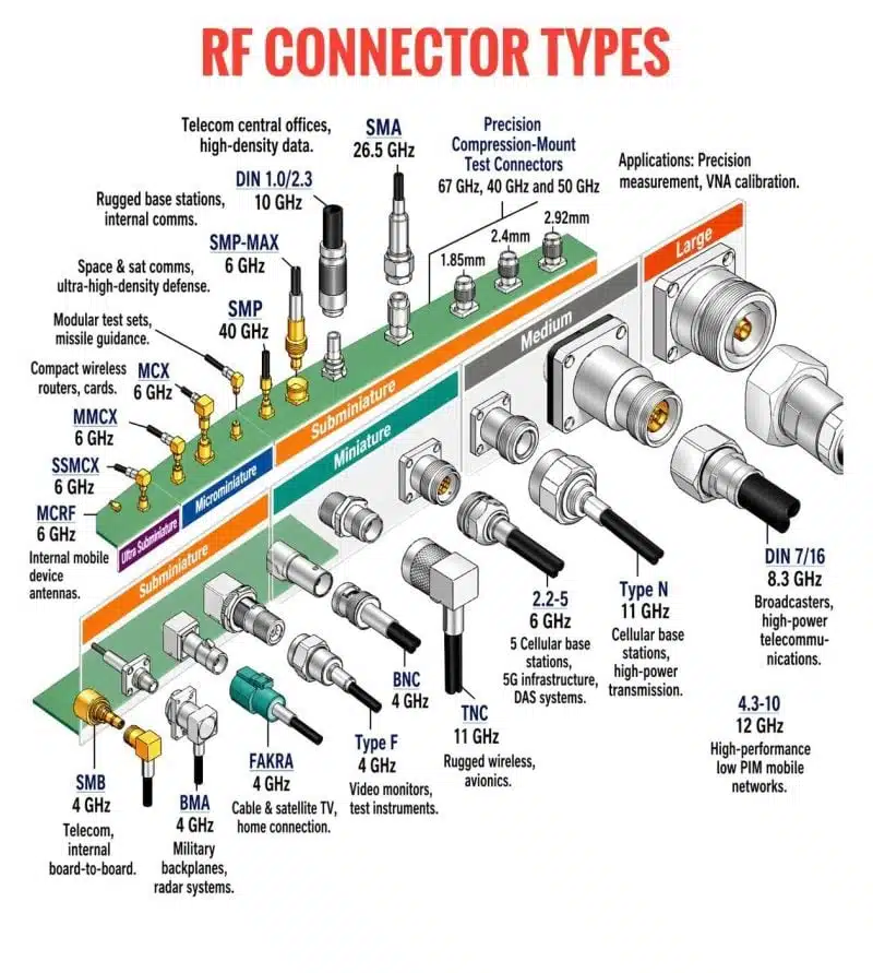
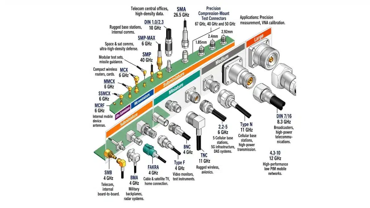
Common RF Connector Families
The table below summarizes key characteristics of widely used connector types (values are typical, individual series and manufacturers may differ).
| Connector | Typical impedance | Usable frequency range | Coupling style | Typical applications |
|---|---|---|---|---|
| SMA | 50 Ω | DC to 18 GHz, up to ~26.5 GHz for precision types | Threaded | General RF/microwave, antennas, lab test, filters, attenuators |
| SMB | 50 Ω / 75 Ω | DC to ~4–12 GHz depending on variant | Push‑on / snap‑on | RF modules, instruments, where quick connect is needed |
| MCX | 50 Ω | DC to ~6–12 GHz | Snap‑on | Compact wireless, GPS, portable devices |
| MMCX | 50 Ω | Up to around 6–12 GHz (series‑dependent) | Snap‑on, micro‑miniature | High‑density RF, embedded radios, mobile/IoT modules |
| SMP | 50 Ω | Up to ~40 GHz in high‑end designs | Push‑on, blind‑mate | High‑density board‑to‑board, microwave modules |
| BNC | 50 Ω / 75 Ω | DC to ~2–4 GHz, commonly used below ~500 MHz | Bayonet | Test equipment, video, lab instrumentation, legacy RF |
| TNC | 50 Ω | Up to ~11–12 GHz for standard series | Threaded version of BNC | Outdoor test, RF links where vibration resistance is required |
| N‑type | 50 Ω / 75 Ω | Up to ~11–12 GHz for standard versions | Threaded, weather‑resistant | Base stations, feeders, radar and high‑power RF transmission |
| UHF (PL‑259/SO‑239) | Nominally non‑constant (~50 Ω class) | Practical use typically below ~300 MHz | Threaded, coarse | HF/VHF radio, amateur radio, legacy equipment |
| 7/16 DIN | 50 Ω | Up to ~7–7.5 GHz | Large threaded | Cellular infrastructure, high‑power outdoor systems |
Miniature and micro‑miniature families (MMCX, MCX, SMP)
At the ultra‑compact end, families such as MCX, MMCX and SMP target high‑density and size‑constrained RF systems. They are common in embedded Wi‑Fi/Bluetooth modules, GPS receivers, IoT radios and board‑to‑board interconnects.
- MCX and MMCX provide snap‑on coupling with small footprints, supporting multi‑GHz operation while minimizing impact on PCB real estate and enclosure height.
- SMP extends into the millimeter‑wave region (tens of GHz) with blind‑mate options, making it attractive for modular microwave assemblies and backplane‑like architectures.
These connectors offer excellent electrical performance relative to their size, but are less suited for frequent manual mating or high‑power operation.
SMA and SMB – workhorses for RF and lab use
SMA is arguably the most widely recognized RF connector in modern laboratory and communication equipment. With 50 Ω impedance and threaded coupling, it offers repeatable performance typically specified to 18 GHz, with precision and metrology‑grade variants reaching 26.5 GHz and beyond.
SMA is the default choice in many designs for:
- RF front‑ends, PLL/VCO outputs, filters and attenuators.
- Antenna ports in Wi‑Fi, LTE and microwave systems.1
- Measurement ports on spectrum/network analyzers and signal sources.
SMB provides similar electrical behavior in a smaller, push‑on format, trading mechanical robustness for quick connect/disconnect in dense equipment and instruments. Both 50 Ω and 75 Ω SMB versions exist, and care must be taken to match impedance across the signal chain.
BNC and TNC – user‑friendly test and field connectors
BNC (Bayonet Neill‑Concelman) remains ubiquitous in test labs, video distribution, and general‑purpose measurement setups. It is available in both 50 Ω and 75 Ω versions, with typical ratings up to a few GHz, though many applications operate well below this limit.
Key aspects of BNC:
- Fast quarter‑turn bayonet coupling, ideal for rapid patching on benches and racks.
- 50 Ω variants favored in RF and general test, 75 Ω versions optimized for broadcast and video where low attenuation and minimal distortion are critical.
TNC is essentially a threaded BNC with improved performance at higher frequencies and better vibration resistance, making it suitable for outdoor and mobile environments. Its secure coupling and extended frequency ceiling make it a common choice in RF communication equipment and some antenna feeds.
N‑type, 7/16 DIN and UHF – high‑power and infrastructure
For higher power levels and outdoor installations, Type N, 7/16 DIN and to some extent legacy UHF connectors dominate coaxial feeder and base‑station infrastructure.
- N‑type connectors are threaded and weather‑resistant, with 50 Ω and 75 Ω versions widely used in microwave links, radar systems, and base‑station feeders up to around 11–12 GHz.
- 7/16 DIN connectors, significantly larger, are optimized for multi‑kilowatt RF power in cellular and broadcast infrastructure, typically specified up to the mid‑GHz range and designed for low intermodulation in multi‑carrier systems.
- UHF connectors (PL‑259/SO‑239) pre‑date constant‑impedance designs and are best regarded as low‑frequency (~HF/VHF) connectors used primarily in amateur radio and legacy systems.
These larger formats provide greater creepage distances, better heat dissipation, and robust mechanical engagement for harsh outdoor environments.
50 Ω vs 75 Ω – Matching Impedance to Application
One recurrent theme across connector families is the choice between 50 Ω and 75 Ω impedance. This choice has strong roots in system‑level optimization between power handling, attenuation and characteristic impedance of coaxial lines.
- 50 Ω systems (SMA, most N, many BNC/TNC, SMB, SMA‑based components) are optimized for RF power transmission and general RF/microwave test, offering a compromise between low loss and high power capability.
- 75 Ω systems (common in video BNC, some SMB and N types) minimize attenuation for voltage‑mode signals and are therefore preferred in broadcast, CATV, and some receiver front‑ends.
Using a 50 Ω connector on a 75 Ω line, or vice versa, creates a localized impedance mismatch that generates reflections, standing waves and measurement inaccuracy, although in some low‑frequency or short‑run video applications small mismatches can be tolerated.
Practical Selection Guidelines for Designers
From a passive‑components and RF interconnect perspective, the connector should be treated as an integral part of the transmission line, not an afterthought. A straightforward selection process can be:
- Define impedance and system topology
Decide early whether the architecture is 50 Ω or 75 Ω, and keep connectors, cables, terminations, attenuators and measurement equipment consistent with that choice. - Set frequency and power targets
Use anticipated operating frequency and power levels to narrow candidates (for example, SMA rather than BNC above a few GHz, N or 7/16 DIN instead of SMA for high‑power feeders). - Consider environment and mating cycles
For bench instruments that will be re‑patched constantly, bayonet BNC or threaded SMA may be preferred; for blind‑mate modules or tight spaces, MCX/MMCX or SMP may be more appropriate. - Integrate with PCB and mechanical design
Connector choice impacts PCB launch geometry, ground referencing, panel layout and sealing; poor transitions can negate any benefit gained from premium coax and passive RF components. - Validate with measurement
Characterize critical interfaces using network analysis (S‑parameters, VSWR) to ensure that connector, launch and cable form a consistent 50 Ω or 75 Ω path over the required frequency band.
A simple mental model is: miniature push‑on connectors (MMCX, MCX, SMP) for dense, embedded and very high‑frequency modules; SMA/SMB as general‑purpose RF workhorses; BNC/TNC as user‑friendly test and mid‑frequency interfaces; and N/7‑16 DIN for high‑power infrastructure and outdoor links.