Passive Components Blog
No Result
View All Result
  • Home
  • NewsFilter
    • All
    • Aerospace & Defence
    • Antenna
    • Applications
    • Automotive
    • Capacitors
    • Circuit Protection Devices
    • electro-mechanical news
    • Filters
    • Fuses
    • Inductors
    • Industrial
    • Integrated Passives
    • inter-connect news
    • Market & Supply Chain
    • Market Insights
    • Medical
    • Modelling and Simulation
    • New Materials & Supply
    • New Technologies
    • Non-linear Passives
    • Oscillators
    • Passive Sensors News
    • Resistors
    • RF & Microwave
    • Telecommunication
    • Weekly Digest

    Advances in the Environmental Performance of Polymer Capacitors

    Vishay Releases DLA Tantalum Polymer Capacitors for Military and Aerospace

    Vishay Expanded Inductor Portfolio With More Than 2000 Stock Items 

    Paumanok Releases Capacitor Foils Market Report 2025-2030

    Modelithics Welcomes CapV as a Sponsoring MVP

    Wk 40 Electronics Supply Chain Digest

    Benefits of Tantalum Powder Stress–Strain Curve Evaluation vs Conventional Wet Test

    Electrolyte Selection and Performance in Supercapacitors

    Connector PCB Design Challenges

    Trending Tags

    • Ripple Current
    • RF
    • Leakage Current
    • Tantalum vs Ceramic
    • Snubber
    • Low ESR
    • Feedthrough
    • Derating
    • Dielectric Constant
    • New Products
    • Market Reports
  • VideoFilter
    • All
    • Antenna videos
    • Capacitor videos
    • Circuit Protection Video
    • Filter videos
    • Fuse videos
    • Inductor videos
    • Inter-Connect Video
    • Non-linear passives videos
    • Oscillator videos
    • Passive sensors videos
    • Resistor videos

    Connector PCB Design Challenges

    Efficient Power Converters: Duty Cycle vs Conduction Losses

    Ripple Steering in Coupled Inductors: SEPIC Case

    SEPIC Converter with Coupled and Uncoupled Inductors

    Coupled Inductors in SEPIC versus Flyback Converters

    Non-Linear MLCC Class II Capacitor Measurements Challenges

    Percolation Phenomenon and Reliability of Molded Power Inductors in DC/DC converters

    Root Causes and Effects of DC Bias and AC in Ceramic Capacitors

    How to Calculate the Output Capacitor for a Switching Power Supply

    Trending Tags

    • Capacitors explained
    • Inductors explained
    • Resistors explained
    • Filters explained
    • Application Video Guidelines
    • EMC
    • New Products
    • Ripple Current
    • Simulation
    • Tantalum vs Ceramic
  • Knowledge Blog
  • Suppliers
    • Who is Who
  • Events
No Result
View All Result
Passive Components Blog
No Result
View All Result

DC/DC Converters

28.2.2018
Reading Time: 5 mins read
A A

A1 DC/DC Converters

A1.1 Capacitors

Today, one can hardly find a consumer, industrial or high reliability electronic device that does not make use of a voltage regulator. Designers basically use two types of regulators, linear LDO (low dropout) and step-down switch-mode DC/DC regulators to convert voltage to lower level. Switching DC/DC regulators are preferred for applications that require a greater difference between input and output voltages because they are more efficient in such operating conditions.

A1.1.1 Switching DC/DC Power Regulators

Switched-mode power supplies (SMPS) are commonly found in many electronic systems. Important SMPS requirements are a stable output voltage with load current, good temperature stability, low ripple voltage and high overall efficiency. One key component in switching power systems is the output capacitor – used to store the charge and for smoothing and therefore its careful selection plays a vital role in determining the overall parameters of the power supply.

RelatedPosts

Advances in the Environmental Performance of Polymer Capacitors

Vishay Releases DLA Tantalum Polymer Capacitors for Military and Aerospace

Vishay Expanded Inductor Portfolio With More Than 2000 Stock Items 

There are typical SMPS topologies shown in Figure 1.

SMPS are used for VIN-to-VOUT transformation:

  • VOUT > VIN, realized by step-up, flyback or SEPIC converters,
  • VOUT < VIN, realized by step-down, flyback or SEPIC converters,
  • VOUT = VIN, realized by flyback or SEPIC converters,
  • VOUT = -VIN, realized by an inverting converter.

An SMPS circuit consists of these specific parts:

  • one or more switching transistors, mainly enhancement-mode MOS-FETs,
  • input and output smoothing capacitors,
  • low-loss passive device(s) accumulating electromagnetic energy (inductors, capacitors, transformers),
  • non-linear rectifying devices (plain P-N or Schottky diodes),
  • control sub-circuit for switching transistor management, feedback stability, and shut-down functionality.

step downsynchronous step down

step upsynchronous step up

synchronous step downSEPIC

flybackinverter

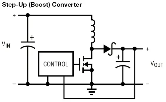
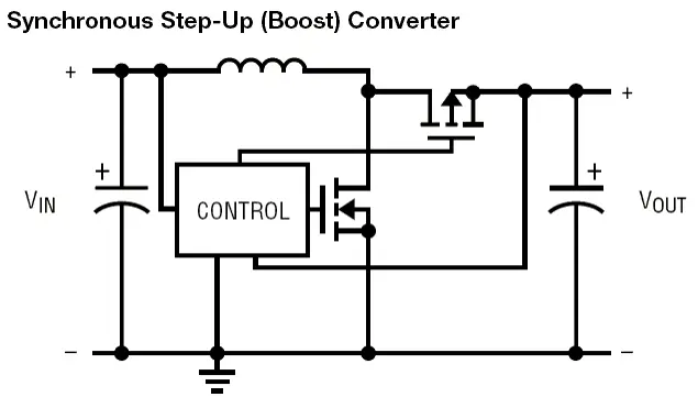
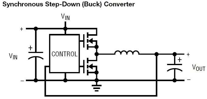
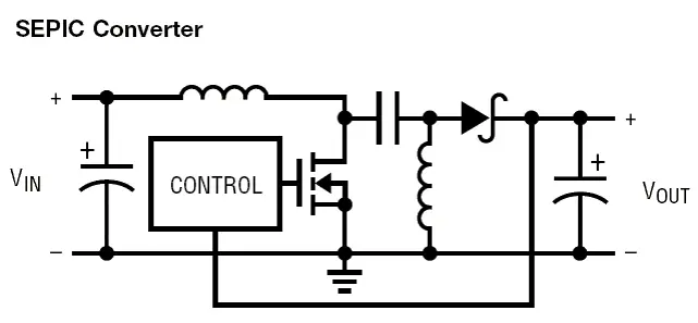
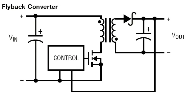
Figure 1 : Typical SMPS topologies:

a) Step-down (buck) converter; b) Synchronous step-down (buck) converter

c) Step-up (boost) converter;d) Synchronous step-up (boost) converter

e) Synchronous step-down-up (buck-boost) converter; f) Single ended primary inductor converter (SEPIC)

g)Flyback isolated-output converter; h) Inverting converter (inverter)

Capacitor Requirements

Input Capacitors

The main purpose of the input capacitors is RF noise suppression and energy reserve. Various capacitor technologies can be used per the application conditions mainly:

  • DC source coupling
  • DC source impedance
  • DC source loading
  • switching frequency

The most of application may be occupied today by MLCC capacitors, some attention has to be paid by selection of the right capacitance value due to the drop of capacitance with DC voltage and small AC ripple. Aluminium capacitors could be used for larger consumer and industrial applications, where larger physical size may not be of concern. An attention has to be paid to the maximum allowed ripple current per the ESR / type of the aluminium capacitors, ussually lower ESR type may be more suitable. Tantalum solid capacitors with MnO2 may not be generally recommended for the input side due to the spike surge current and risk of thermal runaway. Polymer tantalum capacitors may be more suitable to use.

Output Capacitors

The main purpose of the output capacitors is to provide RF noise filtration, voltage and current ripple suppression and function as a local energy reserve for the load. Important application conditions to review for the capacitor selection guide are:

  • local character and sink value
  • storage inductor value
  • converter switching frequency
  • ESR and ripple demands (achievable by single or more caps in parallel)

The general requirements for output capacitors are then:

  • Low ESR
  • High Capacitance
  • Low ESL
  • Capacitance and ESR temperature, voltage and frequency stability

The recommendation for output capacitors would be similar to that for input capacitor with a one difference – the actual surge current load is usually very well stabilised through the feedback loop of the converter, thus the surge current is limited. It is thus safe to use capacitor technologies that are more sensitive to surge load such as tantalum capacitors with MnO2.

A1.1.2. LDO Low Drop-Out Regulators

There are two functions of a capacitor connected to an output of LDO:

  • Local electrical energy reserve
  • RF noise coupling to ground
  • Feedback stability factor for LDO

Simplified structure of LDO with external input/output capacitor and feedback resistors is shown in Figure 2.

LDO

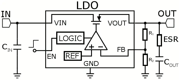
Figure 2 : Simplified LDO and typical external components

It is commonly known that output capacitor influence the gain & phase margin of the LDO loop and thus stability of the LDO see Fig.3. The output capacitance and ESR value with a connected load and its parameters are of the critical importance for the LDO operation.

LDO feedback

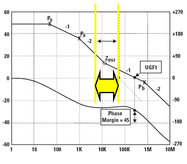
Fig.3. LDO phase and gain stability window that has to be maintained by ESR of the output capacitor

The capacitor’s ESR was the main limitation especially in the case of older LDO circuits where too low ESR of MLCC capacitors could not be used with LDO. The new LDO generation has improved dramatically stability of the loops and it can be said that even MLCC capacitors can be used with LDO now. Nevertheless it is of importance to check the LDO datasheet for the defined capacitor’s ESR working range. It has to be also noted that the ESR stable operation range has to maintained under all environment conditions – it means to count with its stability with temperature, moisture etc.

LDO stability

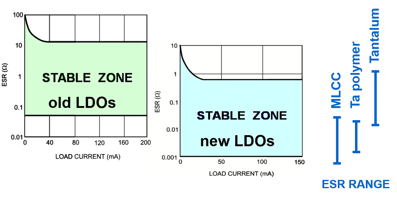
Fig.4. ESR stability window comparison between the older and newer LDO generation.

Traditionally LDOs have been using tantalum output capacitors that provided ideal ESR window and stability. The latest generation of LDOs are mostly allowing use of MLCC capacitors as well, but it is of critical importance to check the LDO specification and ESR characteristics of the selected output capacitor.

more details can be found in technical article [1]


[1] Šponar.R., Faltus.R., Jáně.M.,Flegr.Z. Zednicek.T., “DC/DC Converter Output Capacitor Benchmark”, CARTS Europe 2008


rev.1: source: T.Zednicek EPCI

Related

Recent Posts

Advances in the Environmental Performance of Polymer Capacitors

8.10.2025
2

Benefits of Tantalum Powder Stress–Strain Curve Evaluation vs Conventional Wet Test

3.10.2025
20

Electrolyte Selection and Performance in Supercapacitors

3.10.2025
16

Connector PCB Design Challenges

3.10.2025
20

Researchers Demonstrated High Energy Ceramic Capacitors Stable in Wide Temperature Range

2.10.2025
24

How to Manage Supercapacitors Leakage Current and Self Discharge 

1.10.2025
39

Experimental Evaluation of Wear Failures in SMD Inductors

1.10.2025
36

Resonant Capacitors in High-Power Resonant Circuits

1.10.2025
37
a Schematic diagram of the BNT-based components constructed based on the entropy-increase strategy. b Digital photograph, cross-sectional SEM image, and EDS mappings of the MLCCs. c Unipolar P-E loops of MLCCs as a function of applied E. d Wrec and η of the MLCCs as a function of applied E. The comparison of (e) Wrec and η, (f) η and UF of the MLCCs with those of other recently reported state-of-the-art MLCCs. source: Nature Communications

Researchers Proposed Enhanced Energy Storage MLCC

1.10.2025
18

Improving SMPS Performance with Thermal Interface Material

30.9.2025
12

Upcoming Events

Oct 14
16:00 - 17:00 CEST

Smart Sensors, Smarter AI: Building Reliable Edge Systems

Oct 17
12:00 - 14:00 EDT

External Visual Inspection per MIL-STD-883 TM 2009

Oct 20
October 20 - October 23

Digital WE Days 2025 – Virtual Conference

Oct 21
October 21 @ 12:00 - October 23 @ 14:15 EDT

Space and Military Standards for Hybrids and RF Microwave Modules

Oct 28
8:00 - 15:00 CET

Power Up Your Design: SN6507 and the Ready-to-Use Development Kit

View Calendar

Popular Posts

  • Buck Converter Design and Calculation

    0 shares
    Share 0 Tweet 0
  • Boost Converter Design and Calculation

    0 shares
    Share 0 Tweet 0
  • Flyback Converter Design and Calculation

    0 shares
    Share 0 Tweet 0
  • LLC Resonant Converter Design and Calculation

    0 shares
    Share 0 Tweet 0
  • SEPIC Converter Design and Calculation

    0 shares
    Share 0 Tweet 0
  • Dual Active Bridge (DAB) Topology Explained

    0 shares
    Share 0 Tweet 0
  • Ripple Current and its Effects on the Performance of Capacitors

    3 shares
    Share 3 Tweet 0
  • What is a Dielectric Constant and DF of Plastic Materials?

    4 shares
    Share 4 Tweet 0
  • Flying Capacitors Explained

    0 shares
    Share 0 Tweet 0
  • MLCC and Ceramic Capacitors

    0 shares
    Share 0 Tweet 0

Newsletter Subscription


Passive Components Blog

© EPCI - Leading Passive Components Educational and Information Site

  • Home
  • Privacy Policy
  • EPCI Membership & Advertisement
  • About

No Result
View All Result
  • Home
  • Knowledge Blog
  • Premium Suppliers

© EPCI - Leading Passive Components Educational and Information Site

This website uses cookies. By continuing to use this website you are giving consent to cookies being used. Visit our Privacy and Cookie Policy.
Go to mobile version