


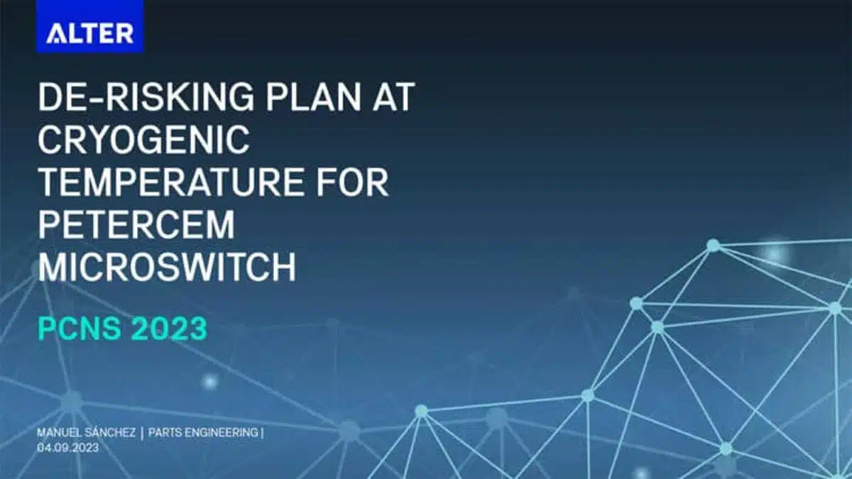
The challenge of Space operating components increases from one year to another. This paper study capability and physical mechanisms of microswitch manufactured by PETERCEM to operate at different temperature ranges (cryogenic, ambient and a transition temperature from cryogenic to ambient).
The paper was presented by Manuel Sánchez Ruiz, Alter, Sevilla, Spain at the 4th PCNS 10-14th September 2023, Sønderborg, Denmark as paper No. 3.3.
Introduction
The challenge of Space business increases from one year to another due to the increasing complexity of the mission objectives and the instruments involved. As a result of this, high stringent environmental requirements are arising more often.
Following this trend, ESA’s ARIEL (Atmospheric Remote-sensing Infrared Exoplanet Large-survey, ESA Cosmic Vision M4) science mission includes a Cold Payload Module (PLM), which comprises some instruments working at extreme low temperatures around 40K. M2 Mechanism (M2M), a positioning mechanism manufactured by SENER, is one of these instruments. It allows an accurate motion/adjustment of the secondary mirror of the ARIEL telescope in order to compensate the optical alignment of the telescope. The subsystem includes the pointing mechanism (M2M) and the telescope control unit (TCU) joined by the harness.
In particular, it is of interest the case of the M2M Harness operating at different temperature ranges (cryogenic, ambient and a transition temperature from cryogenic to ambient), where a microswitch manufactured by PETERCEM (FR) has been selected to know the status of the mechanism at cryogenic temperature values.
This part, previously ESCC QPL in the past, has been introduced as an alternative to Honeywell microswitch for Space, which currently has a long lead time (more than 40 weeks). On the other hand, it is still to be proven that the part manufactured by PETERCEM is able to withstand cryogenic temperatures.
For this reason, a de-risking plan, consisting of a functional verification at 40K, has been proposed by ALTER with review and agreement of SENER and ESA in order to test some samples and get some de-risking results that should give some confidence before submitting this part to a proper qualification according to the missions’ requirements. The di-risking test results should confirm that the Petercem microswitch is a valuable alternative to Honeywell microswitch.
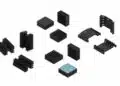
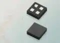
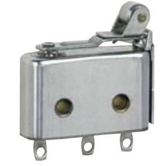
Parts Description
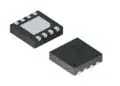
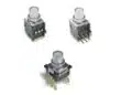
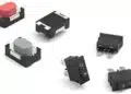
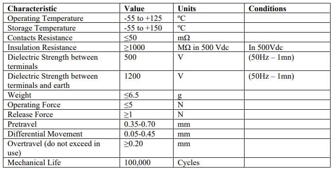
The component under test is an electro-mechanical microswitch, hermetically sealed with an internal nitrogen atmosphere, with part number T6932 (previously ESCC 370100302B) manufactured by PETERCEM.
On an electrical sense, the current values are as follows:
| Voltage / Circuit Type | Resistant | Inductive | Qualified Life |
| 115 Vac (400Hz) 28 Vdc 3 Vdc 30 mVdc | 1 A 4 A 100 µA 10 mA | 1 A (L/R < 5 ms) | 10,000 cycles 40,000 cycles |
Table 2: Current values per voltage level and circuit type
The 4 samples used for this characterization are parts in stock coming from a lot used on SENTINEL-1 mission. The date code of the parts is DC 1640, and the following table shows which was the original use of these parts within the lot as well as the serial number of each part:
| Serial Number | Originally Used For |
| 1640067 | Control Sample |
| 1640069 | Set-up Sample |
| 1640088 | Chart V LAT Level 3 |
| 1640091 | Chart V LAT Level 3 |
| 1640110 | Set-up Sample |
Table 3: Samples used for the test and their original use
Test Flow Description
From the parts taken from SENTINEL-1 stock, 4 samples were used in the testing: 1 part as Control Sample and 3 additional Samples for the actual testing. The Flow is shown in Figure 2:
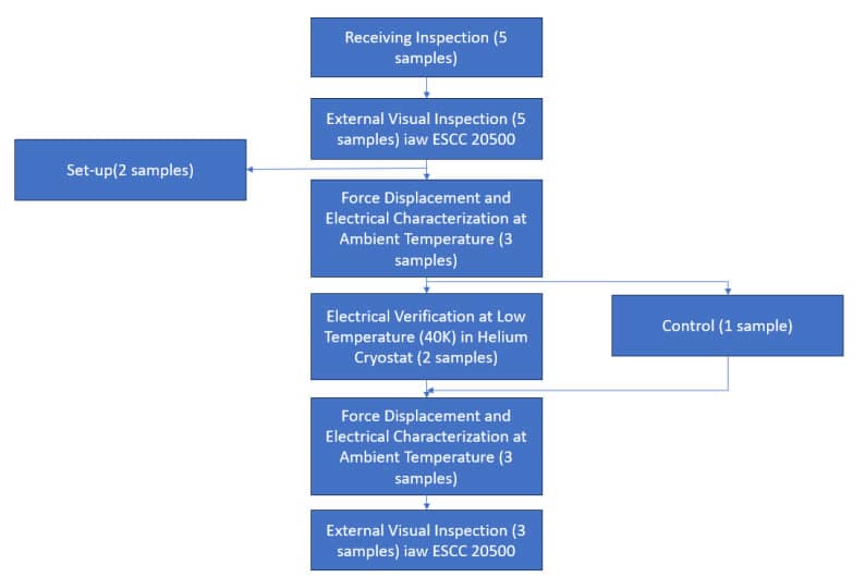
Thus, the characterization of the microswitches at 40 K will be done as follows:
- First, the force-displacement and electrical measurement of contact resistance at room temperature without mounting the samples in the set-up is measured.
- Then, samples will be placed under test in the set-up avoiding the contact with the switching tool (red piece shown on Figure 5 below). This is necessary to prevent the heat dissipation through the linear feedthrough. After that, samples will be cooled until 40K.
- Then, manual movement of the linear feedthrough while monitoring the electrical contacts of the switch or switches under test will be made. The ON-OFF switching will be repeated 5 times for repeatability purposes.
- Afterwards, parts will be heated again until they reach ambient temperature.
- Finally, the force-displacement and electrical measurement of contact resistance at room temperature will be repeated for comparison with the first step after the cooling-heating process and results obtained will be analysed.
Test Set-up and Equipment
The testing is performed at ALTER facilities in Madrid, Spain, by our experts, making use of a Helium cryostat capable of reaching the extremely low temperatures of 40K that the test flow requires. The setup makes use of a linear motion feedthrough that allows switching the samples while monitoring the electrical characteristics (Figure 3). This setup allows a switching cycle to be completed in approximately 5 seconds.
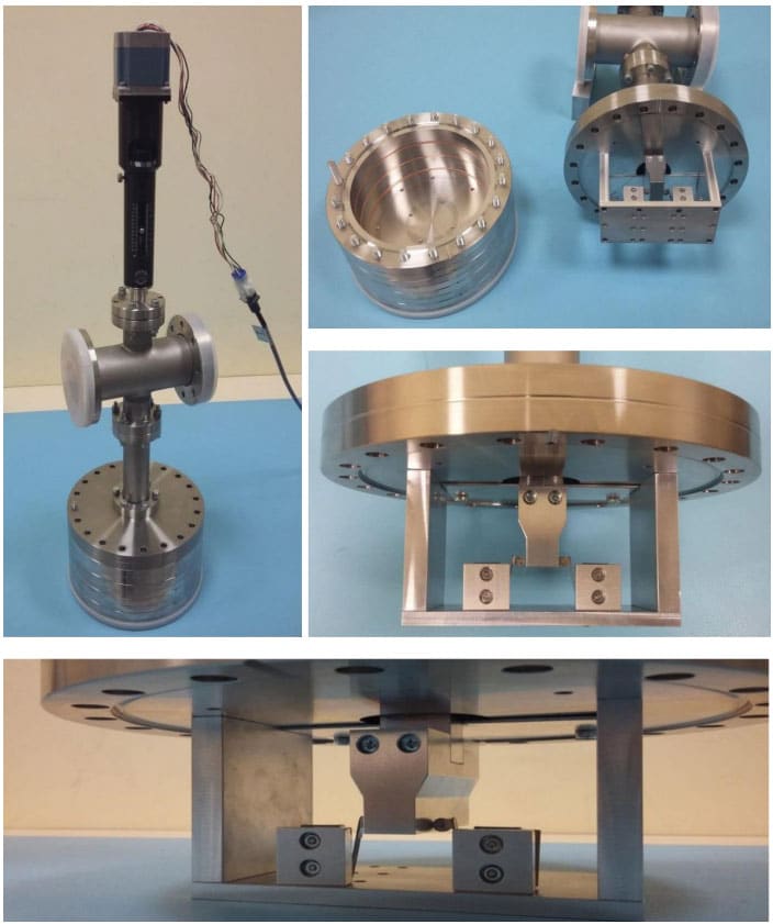
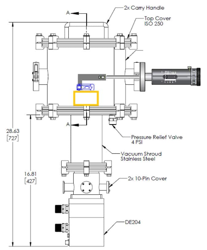
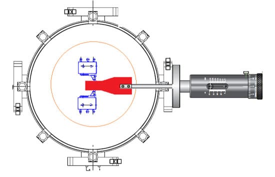
A similar setup was coupled with the Helium cryostat to allow the characterization of the switches at the required temperature. Figure 4 shows a drawing of the helium cryostat with the linear motion feedthrough coupled to one of the lateral ports of the vacuum system to allow the movement of the metal piece that will move the switch. The electrical behaviour of the switch will be monitored by means of the electrical feedthroughs.
To finish, the drawing on Figure 5. shows a schematic of the set-up proposed to mechanically switch two samples at the same time, allowing self-centring of the linear feedthrough.
Results and Analysis
In relation to the test flow already described, it is here presented the results obtained for each step:
- Initial External Visual Inspection: None of the samples received showed any defects.
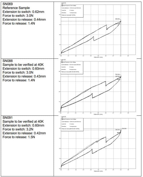
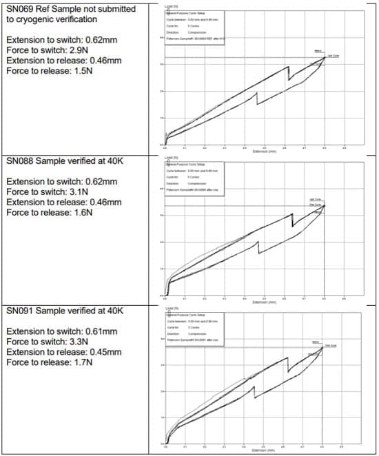
- Initial Force – Displacement (before cryogenic verification):
Verification at 40K: Figure 7 shows the evolution of the temperature (left axis) monitored during the cooling with the Helium cryostat and the resistance (right axis) of the NO (Normally Open) and NC (Normally Close) contacts of the two samples under test. Both samples switched properly repetitively at 40K and at room temperature before and after the cryogenic verification.
Note that the resistance measurements were done with 2 wires connection and therefore it includes the wires and feedthrough resistance. An additional verification of the switching capability was performed during the cooling phase at 70K approximately to verify the correct behaviour of the setup. Two anomalies can be observed around the switching at 70k and in the end, with resistance values of 0 Ohm, which is not a possible value considering the measurements include wires and feedthrough resistance. The most likely cause is the manipulation of the equipment by the technician or some
reset of the measurement equipment.
The graphs show that this phenomenon is common to the measurements of the two samples, which would support this theory, considering it is not a related to any of the samples, and that both of them have been measured simultaneously.
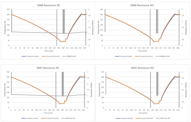
Figure 7 shows that, for both samples, the NC contacts line starts at a certain value (around 1 Ohm), and rises to infinity when switching. On the other hand, for the NO contacts, the graphs show the opposite, starting on infinity values and going down to around 1 Ohm when switching. For practical purposes, the resistance scale on the graphs has been limited to 3 Ohm, although the data obtained shows correct values.
In relation to the resistance value obtained when contacts are closed, it is of interest to note that it is way higher than 50 mOhm, (contact resistance of the microswitch), which is in line to the fact that the measurements also account for the feedthrough and the cables resistance.
Figure 8 shows a detail of the five times switching verification at 40K:
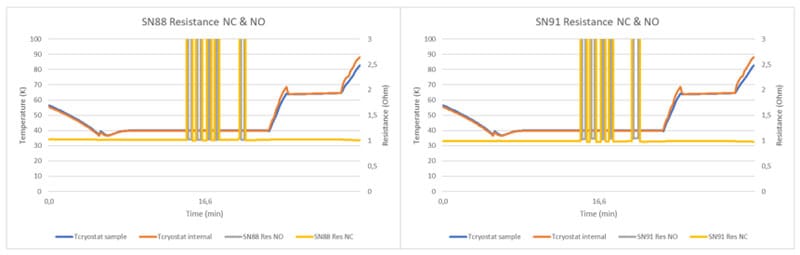
As it can be seen in Figure 8, the graphs of the NC and NO contacts matches perfectly for each of the samples.
- Final Force – Displacement (after cryogenic verification):
- Final External Visual Inspection: None of the samples showed any defects.
As it can be seen according to the figures presented, the force-displacement values of each of the microswitches are not affected by the temperature, so the results obtained are quite similar between the initial and the final measurements, with little deviation.
In relation to the electrical characterization at 40K, the resistance values stay reasonably steady during the whole period of the test, even in the cryogenic temperature range, only being affected by the switching cycles.
Conclusion
The testing performed cannot substitute a deeper evaluation at cryogenic temperatures that can provide an assurance for the use of this microswitch on the cryogenic temperature range for Ariel mission. However, the testing performed and the results obtained provide a first positive feedback that can support the initial selection of the component and the procurement of the flight batch.
Acknowledgements
We would like to thank Dr. Léo A. Farhat from ESA for his support and collaboration in the requirements and test definition. We would also like to thank SENER Aeroespacial for their support on providing the test samples.