Safety capacitors (see quick guide here) also known as interference suppression capacitors, are permanent fixtures in power packs and power supplies. They are used in every household with the broad use of switching power supplies in computers, printers, televisions, and chargers for mobile phones, among other applications. They are also seeing increased use in the automotive industry due to the electrification of vehicles and their increasingly high power-supply voltages, which make new requirements necessary. Florian Weyland, manager of product marketing, ceramic capacitors, at Vishay Intertechnology explains the considerations of its used in article published by Electronic Products.
Globally, automobile manufacturers are under pressure to advance the electrification of their vehicles. This does not just mean installing new driver-assistance systems in the vehicle but bringing battery-operated electric vehicles (EVs) whether hybrid (HEV) or completely electric, to market.
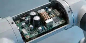
Legislators are pushing this trend with conditions for reducing carbon dioxide emissions. The use of electric motors presupposes exchanging classic fuels such as gasoline or diesel for electrochemical energy storage systems such as batteries. As is known, batteries are not charged at the gas pump but, instead, at a power outlet or a charging station using direct voltage. To do this, the vehicle needs charging electronics, also known as on-board chargers (OBCs), with appropriate AC/DC conversion.
In this respect, these chargers can be compared with mobile phones and their power supplies, just at a higher power level and with considerably higher energy density. However, some of the requirements for safety capacitors in the automotive industry are different, which is why special, automotive-qualified safety capacitors must be used for OBCs.
General requirements
Safety capacitors conduct high-frequency interference signals — electromagnetic interference (EMI) and radio-frequency interference (RFI) — to chassis ground or the neutral conductor, which short-circuits this interference. Reducing EMI ensures electromagnetic compatibility (EMC). In addition, safety capacitors must intercept excessive voltages on the power supply side, preventing coupling in the electrical supply system. These safety capacitors are divided into two classes — X capacitors and Y capacitors.
X capacitors are connected between a phase and the neutral conductor. In this case, a capacitor failure won’t result in a dangerous electric shock. Within Class X devices, there is another subdivision into X1 and X2 capacitors. According to the regulation, Class X1 capacitors must withstand pulses up to 4 kV and X2 capacitors must withstand pulses of 2.5 kV.
Class Y safety capacitors are used between the phase or neutral conductor and the accessible device housing. In this case, the base insulation is bypassed and, in the event of a safety capacitor failure, people may be put in danger. For this reason, it is necessary for Class Y safety capacitors to have increased electrical safety. Within Class Y, there is also a subdivision into Y1 and Y2 safety capacitors. Y1 safety capacitors must withstand a voltage pulse of 8 kV and Y2 safety capacitors must withstand a pulse of 5 kV.
Safety capacitors are subject to the IEC 60384-14 standard and must be tested and certified by an official agency.
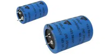
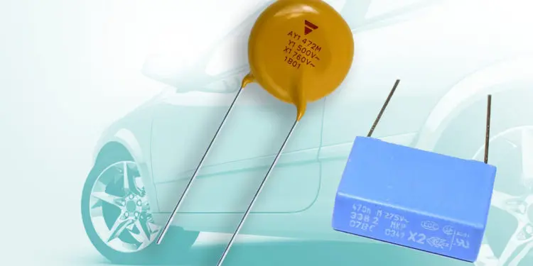
Safety capacitors come in various designs, including film capacitors, ceramic disc capacitors, or multilayer ceramic capacitors (MLCCs). In these versions, film capacitors provide the advantages of high achievable capacitance, stable capacitance, and a stable dissipation factor over the usable temperature range. In addition, metalized film capacitors have a self-healing effect. In the event of a breakdown due to a fault in the film, a small arc occurs if voltage is applied. This arc causes oxidation around the damaged point in the aluminum coating of the film. This process isolates the damaged point, preventing greater damage.
Film capacitors are the first choice as Class X capacitors thanks to their self-healing properties. Ceramic disc capacitors, on the other hand, provide the highest voltage immunity and are the preferred solution for Class Y1 applications.
Special requirements in the automotive industry
MLCCs are also suitable as Class X or Class Y capacitors. However, they satisfy only the requirements of automotive-qualified safety capacitors as Class X1 or Class Y2 components.
The capacitor type considered for the charging electronics in an EV/HEV vehicle depends on its circuitry, the expected voltage pulses, and the alternating voltages applied across the safety capacitor.
There are also automotive-qualified film and ceramic capacitors that even exceed the automotive requirements. How that works is described below.
Automotive qualification
The Automotive Electronic Council (AEC) defines and publishes the requirements placed on electronic components in the automotive industry. The AEC-Q200 requirement describes the tests that passive components must pass.
Vishay Intertechnology, for example, provides two automotive-qualified series of ceramic capacitors. These are the AY1 series that is certified in accordance with Class Y1 and the AY2 series that is certified in accordance with Class Y2. The range of products also includes the MKP3386Y2 and F340Y2 series of Class Y2 film capacitors and the F339X2, MKP339, and F1772 series of Class X2 film capacitors that all comply with the requirements of the automotive industry.
An appropriate design for low and high temperatures is also required for safety capacitors. Consequently, ceramic capacitors are typically designed to operate over the temperature range of –55°C to 125°C and film capacitors over the range of –55°C to 85°C or 105°C (125°C under development). As the probability of component failure increases with increasing temperature, the components are tested at their maximum allowed temperatures.
This means the capacitors must be tested for at least 1,000 hours at the maximum design voltage. Vishay exceeds these requirements with the AY2 ceramic capacitor line, which survives 3,000 hours reliably under these conditions.
In addition, the components must survive 1,000 temperature cycles between –55°C and 125°C for ceramic capacitors and between –55°C and 85°C or 105°C for film capacitors. In the event of large temperature cycles with fast temperature changes (from the minimum design temperature to the maximum design temperature in less than one minute), the thermal expansion or contraction may result in cracks or delamination inside the capacitor or part of the cover may separate from the capacitor.
Automotive-qualified capacitors are designed so that they can survive these external conditions. The design of the components also makes them suitable for non-automotive applications that need increased safety with respect to temperature fluctuations.
Moisture resistance is just as necessary. For this, ceramic capacitors must survive a maximum design voltage for 1,000 hours at 85°C and 85% relative humidity. At increased temperature and humidity, water can penetrate the cover. This occurs by diffusion through the coating material or, primarily, at the transition between the coated and the uncoated wire. The penetrating moisture can cause short-circuits in the capacitor.
To prevent this and to ensure moisture resistance, the coating material and the covering process are adapted to the automotive application. The requirements for film capacitors are 40°C and a relative humidity of 93% with the rated voltage applied for 1,000 hours. The F340Y2 series from Vishay, as an example, is designed for the extreme conditions, exceeding requirements at 85°C, 85% relative humidity, and rated voltage for 1,000 hours.
The mechanical requirements put on electronic components in the automotive market, such as robustness against vibrations and mechanical impacts, are also higher than in other applications. Vishay Intertechnology allows for this with its automotive-qualified safety capacitors.
In summary, safety capacitors, segmented into Class X and Class Y types, filter out high-frequency interference signals (EMC) and protect circuits and users from high-voltage surges. Automotive-qualified capacitors are designed to survive extreme environmental conditions. The necessity of certification by authorized agencies goes hand in hand with the safety-critical nature. The AEC publishes regulations for tests that must be passed for automotive applications.
About the author
Florian Weyland currently serves as manager of product marketing, ceramic capacitors, at Vishay Intertechnology. He is a member of the German Ceramic Society, winner of its Hans- Walter-Hennicke Award, and recipient of its grant for the 2017 American Winter Workshop. Mr. Weyland holds a Dr.Ing. from the TU Darmstadt.


