Passive Components Blog
No Result
View All Result
  • Home
  • NewsFilter
    • All
    • Aerospace & Defence
    • Antenna
    • Applications
    • Automotive
    • Capacitors
    • Circuit Protection Devices
    • electro-mechanical news
    • Filters
    • Fuses
    • Inductors
    • Industrial
    • Integrated Passives
    • inter-connect news
    • Market & Supply Chain
    • Market Insights
    • Medical
    • Modelling and Simulation
    • New Materials & Supply
    • New Technologies
    • Non-linear Passives
    • Oscillators
    • Passive Sensors News
    • Resistors
    • RF & Microwave
    • Telecommunication
    • Weekly Digest

    Modelithics Releases COMPLETE v26.1 for Keysight ADS

    April 2026 Interconnect, Passives and Electromechanical Components Market Insights

    SPICE Simulation of Non-Linear Resistors: Vishay’s Thermistor and PPTC Modelling Ecosystem

    KYOCERA AVX Introduces Traction‑Grade DC Link Film Capacitors

    When More Capacitance Hurts Reliability: The Role of the Metallic Skeleton in Tantalum Anodes

    Why Power Inductors Use a Ferrite Core With an Air Gap

    Wk 16 Electronics Supply Chain Digest

    YAGEO Introduces High‑Current Y2/X1 Film Capacitors for Wide-bandgap Power Systems

    Amphenol Explanded Liquid Cooling Connectors for AI, ESS and EV Systems

    Trending Tags

    • Ripple Current
    • RF
    • Leakage Current
    • Tantalum vs Ceramic
    • Snubber
    • Low ESR
    • Feedthrough
    • Derating
    • Dielectric Constant
    • New Products
    • Market Reports
  • VideoFilter
    • All
    • Antenna videos
    • Capacitor videos
    • Circuit Protection Video
    • Filter videos
    • Fuse videos
    • Inductor videos
    • Inter-Connect Video
    • Non-linear passives videos
    • Oscillator videos
    • Passive sensors videos
    • Resistor videos

    Why Power Inductors Use a Ferrite Core With an Air Gap

    Transformer-Based Power-Line Harvester Magnetic Design

    Thermal Modeling of Magnetics

    Standard vs Planar LLC transformers Comparison for Battery Chargers

    How Modern Tools Model Magnetic Components for Power Electronics

    Advanced Loss Modeling for Planar Magnetics in the Frenetic Planar Tool

    2026 Power Magnetics Design Trends: Flyback, DAB and Planar

    Enabling Software‑Defined Vehicle Architectures: Automotive Ethernet and Zonal Smart Power

    Calculating Resistance Value of a Flyback RC Snubber 

    Trending Tags

    • Capacitors explained
    • Inductors explained
    • Resistors explained
    • Filters explained
    • Application Video Guidelines
    • EMC
    • New Products
    • Ripple Current
    • Simulation
    • Tantalum vs Ceramic
  • Knowledge Blog
  • DossiersNew
  • Suppliers
    • Who is Who
  • PCNS
    • PCNS 2025
    • PCNS 2023
    • PCNS 2021
    • PCNS 2019
    • PCNS 2017
  • Events
No Result
View All Result
Passive Components Blog
No Result
View All Result

Fusible Resistors vs Fuses Key Differences Explained

5.1.2022
Reading Time: 4 mins read
A A

Hardware electronic designers can use a conventional fuse, or they can use a fusible resistor to protect their circuits. What will work best in the specific application?

Chargers and external power supplies are essential devices for consumer electronics, especially mobile and wearable products. Keeping them powered and charging them fast is very important to the end-users. Example products include tablet computers, personal computers, mobile phones, gaming devices, mp3 players, wireless smartwatches, headphones, fitness monitors and medical monitors. Downtime to recharge these devices interrupts usage, and consumers need faster recharge times for maximum uptime of their devices.

RelatedPosts

Modelithics Releases COMPLETE v26.1 for Keysight ADS

April 2026 Interconnect, Passives and Electromechanical Components Market Insights

SPICE Simulation of Non-Linear Resistors: Vishay’s Thermistor and PPTC Modelling Ecosystem

Faster charging requires a higher power charger or power supply. Higher power requires designers to put greater emphasis on safety while being challenged by cost and size constraints and more stringent efficiency requirements. While most designers realize they need overcurrent protection for their charger or power supply, they may not know that they can take two different approaches to incorporate overcurrent protection into their design.

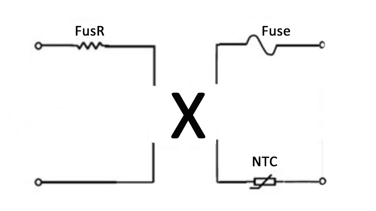
Designers can use a fusible resistor (Figure 1a) or they can use a conventional fuse (Figure 1b)

Figure 1a.: fusible through-hole resistors; source: Vishay
Figure 1b.: SMD fuses; source: Littelfuse

Fusible resistors combine the benefits of overcurrent protection and inrush current protection in one component. However, fusible resistors respond differently to overcurrents and have other impacts on charger and power supply efficiency than fuses.

KEY DIFFERENCES IN BRIEF

Fuses: Reducing the risk of fire by opening at lower temperatures

A fusible resistor opens up like a fuse when its current rating is exceeded. The component is generally a nichrome element with a melting temperature of around 1400° C. Nichrome has a low thermal coefficient of resistance that allows the resistor to have a stable resistance over temperature. The 1400° C melting temperature allows surrounding components and the PC board to get hot during an overcurrent condition.

Fuses are generally copper or silver elements with a melting temperature typically between 962° C and 1083° C. Fuses also have a high thermal coefficient of resistance, at least a factor of 10 higher than a nichrome fusible resistor. As a result, the temperature of a fuse will increase faster when an overcurrent condition occurs. The fuse’s resistance rises more quickly, bringing the fuse to its melting point sooner. A fuse prevents a heat build-up that would otherwise occur when a fusible resistor is subject to an overcurrent condition. The higher heat generated by the fusible resistor can damage other components and potentially lead to the ignition of combustible components near the fusible resistor.

Fusible resistors: Two functions in one package

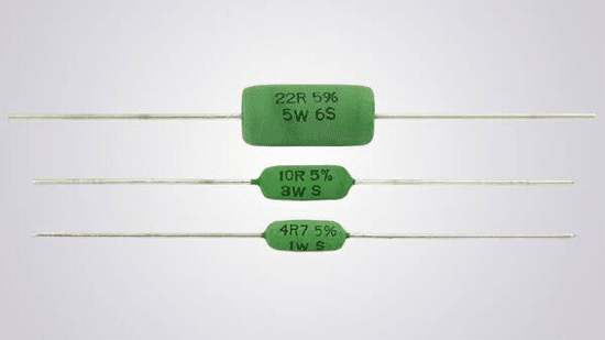
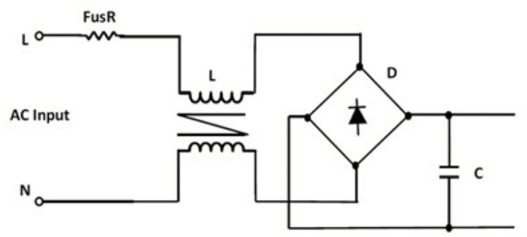
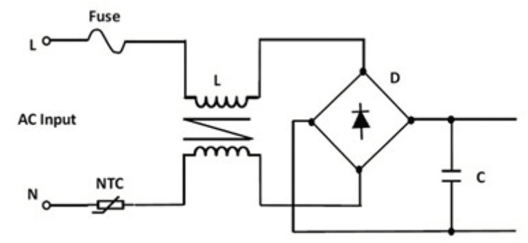
The primary benefit of using a fusible resistor is that its resistance function provides a limitation on inrush current. A fusible resistor used as the main overcurrent component in a power supply or charger (as shown in Figure 2a) can have a resistance of 10 Ω. A fuse, in contrast, has a resistance in the milliohms to 100s of milliohms range. Designers can use a fuse and an NTC thermistor to obtain equivalent overcurrent protection and inrush current limitation (Figure 2b). An NTC thermistor has a resistance that can be as high as 10 or 20 Ω initially; however, it falls into the 10s of milliohm range during steady-state operation of the power supply.

Figure 2a. Power supply/charger circuit using a fusible resistor for overcurrent protection and inrush current limitation. Source: Littelfuse
Figure 2b. Power supply/charger circuit using a fuse for overcurrent protection and an NTC thermistor for inrush current limitation (if needed). Source: Littelfuse

Fusible resistors appear to offer space-saving over using separate fuses and thermistors. However, the heat generated by fusible resistors could require spacing between components. Fusible resistors rated up to 10 W require other parts to be at least 0.5 inch away. If rated above 10 W, and 1 inch spacing is needed. When chargers and power supplies need to be in small, compact packages, the necessary spacing required around the fusible resistors could leave the circuit designer with inadequate space for the complete design.

Related

Source: Electronics360

Recent Posts

Modelithics Releases COMPLETE v26.1 for Keysight ADS

23.4.2026
9

April 2026 Interconnect, Passives and Electromechanical Components Market Insights

22.4.2026
13

When More Capacitance Hurts Reliability: The Role of the Metallic Skeleton in Tantalum Anodes

20.4.2026
25

Why Power Inductors Use a Ferrite Core With an Air Gap

20.4.2026
24

AI-Assisted Structural Diagnostics and Physics-Based Reliability Interpretation of Tantalum Capacitor Anodes

14.4.2026
33

ECIA March 2026 Industry Pulse Points to Best Sales Climate in Five Years

13.4.2026
50

March 2026 Interconnect, Passives and Electromechanical Components Market Insights

2.4.2026
114

APEC 2026 Power Electronics Trends and Implications for Passive Components

1.4.2026
138

Indias ECMS Wave Brings New Capacity For Passive Components Manufacturing in India

31.3.2026
58

Upcoming Events

Apr 27
15:00 - 16:00 CEST

Commercial Space Screening Approach for Agile, High-Reliability Payloads

Apr 29
10:00 - 11:00 CDT

SEPIC Design Done Right

Apr 30
10:00 - 11:00 CDT

Programming Embedded Systems

View Calendar

Popular Posts

  • Buck Converter Design and Calculation

    0 shares
    Share 0 Tweet 0
  • Boost Converter Design and Calculation

    0 shares
    Share 0 Tweet 0
  • Flyback Converter Design and Calculation

    0 shares
    Share 0 Tweet 0
  • LLC Resonant Converter Design and Calculation

    0 shares
    Share 0 Tweet 0
  • MLCC and Ceramic Capacitors

    0 shares
    Share 0 Tweet 0
  • Dual Active Bridge (DAB) Topology

    0 shares
    Share 0 Tweet 0
  • Capacitor Charging and Discharging

    0 shares
    Share 0 Tweet 0
  • What Electronics Engineer Needs to Know About Passive Low Pass Filters

    0 shares
    Share 0 Tweet 0
  • Ripple Current and its Effects on the Performance of Capacitors

    3 shares
    Share 3 Tweet 0
  • MLCC Case Sizes Standards Explained

    0 shares
    Share 0 Tweet 0

Newsletter Subscription


Passive Components Blog

© EPCI - Leading Passive Components Educational and Information Site

  • Home
  • Privacy Policy
  • EPCI Membership & Advertisement
  • About

No Result
View All Result
  • Home
  • Knowledge Blog
  • PCNS

© EPCI - Leading Passive Components Educational and Information Site

This website uses cookies. By continuing to use this website you are giving consent to cookies being used. Visit our Privacy and Cookie Policy.
Go to mobile version