


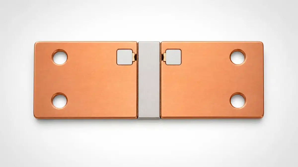
Stackpole Electronics has introduced the HCC series of high current over 1400A busbar shunt resistors, targeting current measurement in battery electric and hybrid vehicle power systems.
These chassis‑mount shunt resistors provide a direct, linear way to monitor very high currents in critical functions such as battery management, DC bus monitoring, and inverter output control, offering an alternative to Hall effect sensors in modern xEV architectures.
Key features and benefits
- High current capability for xEV powertrains
The HCC series covers very low resistance values of 100, 50, and 25 micro‑ohm, enabling current measurement in the range of more than 1400 amps with low power loss in the shunt itself. This makes the series suitable for main battery busbars, traction inverters, and other high current subsystems where both efficiency and measurement accuracy are critical. - Busbar shunt architecture with all‑welded construction
The devices are implemented as busbar‑style shunts with an all‑welded mechanical structure, which provides robust, low‑impedance joints and stable resistance under vibration and thermal cycling. For automotive installations, this type of construction is important to avoid drift or intermittent connections over the vehicle lifetime. - Simple, linear current measurement compared to Hall sensors
Unlike Hall effect sensors, a shunt resistor provides a direct voltage drop proportional to current, which simplifies signal conditioning and calibration. The linear relationship and absence of magnetic cores or active electronics can improve long‑term stability and reduce temperature‑dependent non‑linearities in the measurement chain. - Flexibility in resistance values and geometries
The HCC series is offered with multiple standard resistance values and package sizes, and Stackpole’s vertically integrated manufacturing supports custom sizes, shapes, and resistance values on request. This allows design engineers to match the shunt geometry to their specific busbar layout, creepage/clearance requirements, and target current range. - Cost‑effective solution for high current sensing
Busbar shunts typically offer a cost advantage over integrated sensor modules, especially at very high currents where Hall sensors and similar devices become more complex and expensive. For purchasing teams, the HCC series provides a straightforward way to integrate high current measurement into existing mechanical busbar designs without adding complex electromechanical assemblies.
Summary of key electrical parameters
The available standard resistance values directly define the current range and power dissipation for each HCC shunt variant. Exact current ratings, temperature coefficients, and derating behavior should be taken from the manufacturer datasheet for the specific part number.
| Parameter | Standard options / notes |
|---|---|
| Resistance values | 100 micro‑ohm, 50 micro‑ohm, 25 micro‑ohm |
| Max current capability | More than 1400 A (depending on variant) |
| Construction | All‑welded busbar shunt, chassis mount |
| Customization | Custom sizes, shapes, resistance values |
Values such as allowable temperature rise, continuous vs. peak current, and tolerance are defined per part and should be verified in the official datasheet according to the manufacturer documentation.
Typical applications
The HCC series is aimed primarily at the electrified vehicle market, where accurate high current sensing is required across multiple subsystems.
- Battery management systems (BMS)
The shunts can be used on main battery busbars to measure charge and discharge currents for state‑of‑charge and state‑of‑health calculations. For BMS designers, a stable low‑ohmic shunt at the pack level is essential to maintain accurate coulomb counting over many years of operation. - High voltage DC bus monitoring
In xEV architectures, the DC bus connecting the battery, on‑board charger, DC‑DC converters, and inverters often carries hundreds of amps. Placing an HCC shunt in series with the DC link allows the vehicle control unit to monitor bus current for protection, diagnostics, and efficiency optimization. - Inverter output current measurement
For traction motor drives, measuring the inverter output current supports torque control, efficiency mapping, and fault detection. A busbar shunt on the inverter output can provide a single point of current measurement, which can be combined with phase current sensing or used as a redundant measurement path. - Auxiliary high current subsystems
Beyond traction and main battery circuits, the HCC shunt can be used in other high current paths such as fast DC charging interfaces, high power DC‑DC converters, or auxiliary power units in hybrid vehicles. In these roles, the robust mechanical design and low resistance ensure minimal impact on system efficiency while supporting reliable monitoring.
Technical highlights
From an engineering perspective, the HCC series combines very low resistance with a mechanically robust chassis‑mount package that integrates naturally into busbar‑based power distribution.
- All‑welded mechanical design
The welded joints minimize additional contact resistance and provide good thermal conduction into the busbar structure. This helps to distribute heat and maintain a predictable temperature profile across the shunt. - Linear, ohmic sensing element
Because the sensing mechanism is purely resistive, the output voltage is directly proportional to current, which simplifies analog front‑end design. Signal conditioning typically involves a differential amplifier or isolated amplifier that scales the microvolt‑level shunt signal up to a range suitable for the ADC. - Scalability via resistance selection
Choosing between 100, 50, and 25 micro‑ohm allows designers to trade sensitivity versus power loss. Higher resistance improves measurement resolution but increases I²R dissipation; lower resistance reduces loss but yields a smaller measurement signal.
The manufacturer notes that detailed performance parameters such as tolerance, temperature coefficient, and maximum temperature rise are defined in the datasheet and should be consulted when finalizing a design.
Shunt selection and I²R loss considerations
In practical designs, the voltage drop and power dissipation across the shunt must be evaluated for the expected current range. The power loss scales with the square of current times resistance, so even micro‑ohm values can generate significant heat at several hundred amps. Engineers should ensure that the chosen HCC shunt value provides sufficient measurement signal while staying within thermal limits specified in the manufacturer documentation.
Design‑in notes for engineers
When implementing the HCC busbar shunt in an xEV powertrain, several practical aspects deserve attention beyond the headline resistance value.
- Mechanical integration and mounting
Ensure that the shunt’s chassis‑mount and busbar interfaces align with the mechanical stack‑up of the battery or inverter. Adequate tightening torque, flat mounting surfaces, and proper contact plating on mating busbars help maintain low contact resistance and mechanical stability over time. - Thermal management and derating
Assess the shunt’s power dissipation at worst‑case current and ambient temperature and compare it with the manufacturer’s specified temperature rise and derating curves. In many xEV applications, forced air cooling is limited, so conduction into the busbar and surrounding structure becomes the primary heat removal path. - Electrical isolation and creepage/clearance
Because the shunt sits in the high voltage path, PCB‑level sensing circuits must be galvanically isolated from the high voltage bus. This usually involves isolated amplifiers, shunt monitors, or isolated ADCs, and the mechanical layout must maintain appropriate creepage and clearance distances according to automotive and safety standards. - Signal conditioning and EMC
The low‑level voltage signal across a micro‑ohm shunt is vulnerable to noise pickup, especially in inverter environments with high dV/dt and dI/dt. Use twisted‑pair or shielded sense leads, Kelvin connections, and differential measurement to minimize error. Filtering and layout techniques should be aligned with automotive EMC requirements. - Calibration and long‑term stability
Even though the HCC shunt provides a linear response, initial tolerance and drift over temperature and lifetime impact measurement accuracy. System‑level calibration at end‑of‑line, combined with periodic in‑field recalibration strategies where applicable, can compensate for these effects. Engineers should use the resistance tolerance and temperature coefficient values from the datasheet to define appropriate calibration margins. - Safety and functional integration
Because the HCC shunt is part of the main current path, failure modes and diagnostic coverage must be considered in the functional safety concept. This may include redundant current sensing paths, plausibility checks against other measurements, and fault detection logic in the BMS or inverter controller.
By addressing these aspects early in the design process, engineers can leverage the HCC series to achieve accurate, reliable high current measurement while meeting automotive safety, EMC, and reliability expectations.
Source
This article is based on information provided by Stackpole Electronics in their official press release for the HCC High Current Chassis Mount Shunt Resistor series and related manufacturer documentation.


