Passive Components Blog
No Result
View All Result
  • Home
  • NewsFilter
    • All
    • Aerospace & Defence
    • Antenna
    • Applications
    • Automotive
    • Capacitors
    • Circuit Protection Devices
    • electro-mechanical news
    • Filters
    • Fuses
    • Inductors
    • Industrial
    • Integrated Passives
    • inter-connect news
    • Market & Supply Chain
    • Market Insights
    • Medical
    • Modelling and Simulation
    • New Materials & Supply
    • New Technologies
    • Non-linear Passives
    • Oscillators
    • Passive Sensors News
    • Resistors
    • RF & Microwave
    • Telecommunication
    • Weekly Digest

    PCNS 2025 Final Program Announced!

    DigiKey Expands Inventory with Over 32,000 Stocking NPIs in Q2 2025

    YAGEO Offers High-Performance Diplexers for Dual-Band Wi-Fi 6E/7Integration

    European Components Distribution (DMASS) Faces Continued Decline in Q2 2025

    TDK Announced Wide Frequency Automotive Wirewound POC Inductors

    Bourns Released Rugged, High-Power TO-247 Thick Film Resistor

    Bourns Announced Shielded Power Inductor with High Saturation and Low Radiation

    Würth Elektronik Expands MagI³C with Variable Step-Down Modules

    KYOCERA AVX Releases 600MHz Band71 Compact SAW Duplexer

    Trending Tags

    • Ripple Current
    • RF
    • Leakage Current
    • Tantalum vs Ceramic
    • Snubber
    • Low ESR
    • Feedthrough
    • Derating
    • Dielectric Constant
    • New Products
    • Market Reports
  • VideoFilter
    • All
    • Antenna videos
    • Capacitor videos
    • Circuit Protection Video
    • Filter videos
    • Fuse videos
    • Inductor videos
    • Inter-Connect Video
    • Non-linear passives videos
    • Oscillator videos
    • Passive sensors videos
    • Resistor videos

    Switched Capacitor Converter Explained

    Understanding Inductor Dot Markings and Their Application in LTspice

    Accelerating Full Bridge LLC Resonant Converter Design with Frenetic AI

    Understanding Switched Capacitor Converters

    Coupled Inductors Circuit Model and Examples of its Applications

    Inductor Resonances and its Impact to EMI

    Highly Reliable Flex Rigid PCBs, Würth Elektronik Webinar

    Causes of Oscillations in Flyback Converters

    How to design a 60W Flyback Transformer

    Trending Tags

    • Capacitors explained
    • Inductors explained
    • Resistors explained
    • Filters explained
    • Application Video Guidelines
    • EMC
    • New Products
    • Ripple Current
    • Simulation
    • Tantalum vs Ceramic
  • Knowledge Blog
  • Suppliers
    • Who is Who
  • Events
No Result
View All Result
Passive Components Blog
No Result
View All Result

How to Simulate MLCC DC BIAS Capacitance Drop with LTSpice

24.8.2022
Reading Time: 6 mins read
A A

Impact of MLCC DC BIAS has been discussed in-depth in recent articles High CV MLCC DC BIAS and AGEING Capacitance Loss Explained, but how to simulate MLCC DC BIAS Capacitance Drop with LTSpice software? Reiner Bidenbach, Analog Devices field applications engineer propose a solution in his article published by Evertiq.

Q: How can I take the DC bias effect of multi-layer ceramic capacitors (MLCCs) into account in circuit simulations?

RelatedPosts

DC BIAS Ageing Impact to X7R MLCC Capacitance Drift Vishay Study

Class II MLCCs – More Detailed Classification or More Specific Default Parameters?

Class-II MLCC DC-Bias Aging Issues in Automotive Applications

A: LTspice’s nonlinear capacitor capabilities and a reasonable model.

This article describes how LTspice simulations can be used to account for the effect of voltage dependence, or DC bias, caused by the use of ceramic capacitors with even smaller and smaller case sizes. Demand for smaller electronic devices with an increasing number of features, combined with reduced current consumption, calls for size constraints on components, including MLCCs. As a result, the effect of the voltage dependence, or DC bias, is also being pushed into focus.

Miniaturization of ceramic capacitors requires higher capacitance values in an increasingly smaller space. To that end, materials with high permittivities (ε) and increasingly thin dielectric insulating layers are being implemented, making it now possible to produce high quality ceramic layers on an industrial scale.

Unfortunately, the permittivity εr = ƒ(→E ) is a function of the electric field strength, and thus the capacitance exhibits a voltage dependence. Depending on the ceramic type and the layer thickness, this effect can be very pronounced. A drop in capacitance to less than 10% of the nominal value at the maximum allowable voltage is no rarity.

In applications that work with a constant voltage applied to the MLCC (for example, decoupling capacitors), the effect can easily be taken into account. As long as the voltage remains constant, the remaining capacitance value can be taken from the data sheet or an online tool provided by the manufacturer.

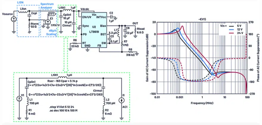
But what about cases in which the voltage is variable—for example, in Figure 4., which shows an input filter on a switching regulator that should be operated with 5 V from USB to 24 V from an industrial supply? Or the AC coupling of a 2-wire Ethernet PHY with supply on the same lines with different voltage values?

In such situations, circuit simulations with LTspice provide useful insight. Some MLCC manufacturers already offer the corresponding DC bias models for down- load. In addition, LTspice provides methods for imitating the voltage-dependent behavior with implemented tools. For this, the curve of capacitance as a function of voltage and one of the approaches described in Figure 3. are useful.

LTspice offers a well-known capacitor model with a constant capacitance as well as a nonlinear model. This nonlinear model evaluates a charge equation. Direct evaluation of a nonlinear capacitance model is unsuitable due to the required charge retention. This should not be a problem here because the capacitance is yielded through differentiation of the charge with respect to the voltage. Conversely, the integral of the voltage-dependent capacitance must be formed. This has already been done for the following approaches, so these models can be used without any math.

The first-order approach uses the linear voltage dependence

linear MLCC capacitance voltage dependence equation [1]

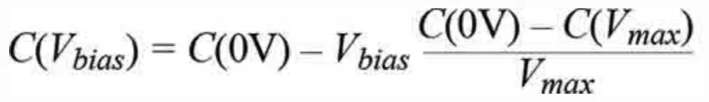
from which, through integration, the charge equation is yielded:

MLCC voltage dependent charge equation [2]

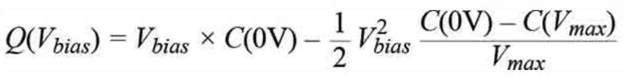
This can now be inserted directly in LTspice nomenclature in place of the capacitance value in the capacitor: Q=x*{c0V}-0.5*x**2*({c0V}-{cVmax})/{Vmax}.

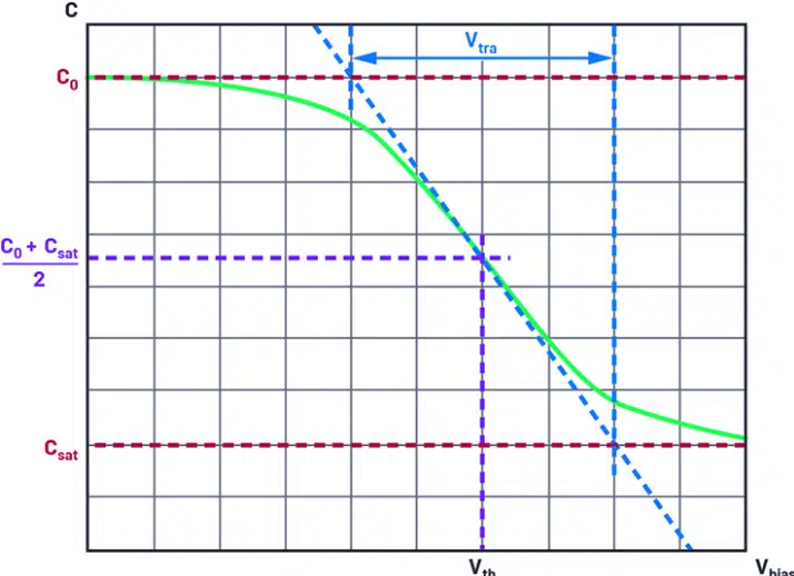
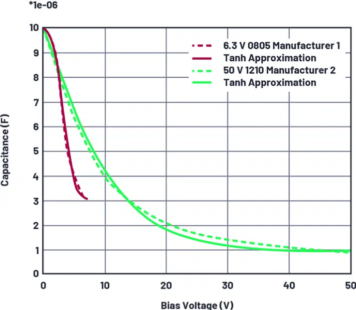
In many MLCCs, however, the initially nearly constant capacitance drops rapidly even at moderate voltages, after which it remains nearly constant. If only the linear model is used in such cases, the effective capacitance is overestimated for a large range of voltages. For this widespread case, a model based on the hyperbolic tangent (tanh) can be used:

LTSpice MLCC capacitance voltage dependence equation [3]

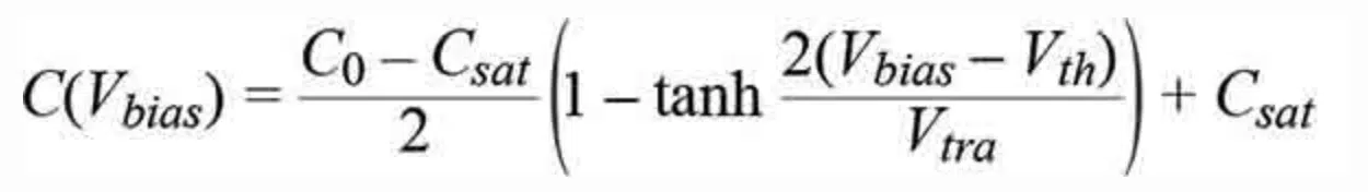
The parameters can be easily estimated without use of further aids – see Figures 1. and 2.

Figure 1. Tanh approximation function and associated parameters.
Figure 2. A 10 µF MLCC Capacitance vs DC BIAS voltage dependence example
Figure 3. An example of a 10 µF 6.3 V 0805 MLCC with various capacitance models in LTspice.

The capacitance value can also simply be replaced by the charge equation:
Q=x*({C0+Csat})/2+({Csat-C0})/4*{Vtra}*ln(cosh((x-{Vth})*2/{Vtra})).

For checking the capacitor model in LTspice, a constant voltage ramp with is applied. The amount of current through the capacitor then corresponds exactly to the capacitance value due to .

Figure 3 clearly shows the superiority of the proposed nonlinear models over the standard constant-capacitance model. With such a capacitance curve, the linear model is sufficient for most applications.

Finally, it should be noted that only a single nonideal effect is simulated here. There are still a number of other effects in MLCCs including aging, temperature dependence, frequency dependence, AC amplitude dependence, dielectric absorption, and many more. For many applications, it is sufficient to consider the DC bias dependence as the only dominant effect. LTspice can be used as a practical tool to account for nonidealities such as DC bias prior to manufacturing the first prototype.

Figure 4. Simulation of the interference current suppression of the input filter of an LT8619 step-down regulator from the converter side for different supply voltages using the tanh model.

Related

Source: Analog Devices, Evertiq

Recent Posts

PCNS 2025 Final Program Announced!

31.7.2025
3

European Components Distribution (DMASS) Faces Continued Decline in Q2 2025

30.7.2025
5

Switched Capacitor Converter Explained

28.7.2025
12

Samsung Releases 1000V 1812 X7R 100nF MLCC for Electric Vehicles

28.7.2025
16

Samsung Electro-Mechanics Releases Molded MLCC Capacitors

28.7.2025
22

Researchers Demonstrated 200C Polymer Film Dielectric

28.7.2025
10

Researchers Demonstrated Zinc-Ion Based Photo-Supercapacitor

28.7.2025
9
Comparative display of a grain size and domain structure; b free energy; c P-E loops after high-entropy ceramics (HECs) and PGS design. source: Nature Communications  ISSN 2041-1723

Researchers Propose Novel MLCC Dielectric Design to Increase Energy Storage Capacity

24.7.2025
38

Samsung Electro-Mechanics Focuses MLCCs on AI servers and Automotive

22.7.2025
56

Modelithics Library Expands with 120 New Models

22.7.2025
4

Upcoming Events

Sep 22
September 22 @ 13:00 - September 25 @ 15:15 EDT

Pre Cap Visual Inspection per Mil-Std-883 (TM 2017)

Sep 30
September 30 @ 12:00 - October 2 @ 14:00 EDT

MIL-Std-883 TM 2010

Oct 17
12:00 - 14:00 EDT

External Visual Inspection per MIL-STD-883 TM 2009

Oct 21
October 21 @ 12:00 - October 23 @ 14:15 EDT

Space and Military Standards for Hybrids and RF Microwave Modules

Nov 4
November 4 @ 12:00 - November 6 @ 14:15 EST

Wirebond Materials, Processes, Reliability and Testing

View Calendar

Popular Posts

  • Buck Converter Design and Calculation

    0 shares
    Share 0 Tweet 0
  • Boost Converter Design and Calculation

    0 shares
    Share 0 Tweet 0
  • Flyback Converter Design and Calculation

    0 shares
    Share 0 Tweet 0
  • LLC Resonant Converter Design and Calculation

    0 shares
    Share 0 Tweet 0
  • What is a Dielectric Constant and DF of Plastic Materials?

    4 shares
    Share 4 Tweet 0
  • Dual Active Bridge (DAB) Topology Explained

    0 shares
    Share 0 Tweet 0
  • Ripple Current and its Effects on the Performance of Capacitors

    3 shares
    Share 3 Tweet 0
  • How to Design an Inductor

    0 shares
    Share 0 Tweet 0
  • MLCC Case Sizes Standards Explained

    0 shares
    Share 0 Tweet 0
  • MLCC and Ceramic Capacitors

    0 shares
    Share 0 Tweet 0

Newsletter Subscription


Passive Components Blog

© EPCI - Leading Passive Components Educational and Information Site

  • Home
  • Privacy Policy
  • EPCI Membership & Advertisement
  • About

No Result
View All Result
  • Home
  • Knowledge Blog
  • Premium Suppliers

© EPCI - Leading Passive Components Educational and Information Site

This website uses cookies. By continuing to use this website you are giving consent to cookies being used. Visit our Privacy and Cookie Policy.
Go to mobile version