


This article provides a practical introduction to how transformers and solenoids work, their key equations, parasitic effects, and typical applications for design engineers and advanced students.
Key Takeaways
- A transformer transfers electric energy between circuits, stepping up or down voltage.
- The ideal transformer operates based on turns ratio, with primary and secondary windings influencing current and voltage.
- Solenoids convert electrical energy into mechanical energy and operate on electromagnetism, with various types such as AC and DC models.
- Magnetic force in solenoids increases with more turns and current, and applications include solenoid valves and locks.
- Design engineers must consider factors like winding geometry and parasitic effects when designing transformers and solenoids.
What is a transformer
A transformer is a device that transfers electric energy from one alternating-current circuit to one or more other circuits, either increasing (stepping up) or reducing (stepping down) the voltage.
Ideal transformer and basic equations
For simplicity, consider first an ideal transformer with 1:1 turns ratio and an open secondary – see Figure 1.
A transformer consists of at least two windings, with the winding turns NP on the primary side and NS on the secondary side.
In a first step, we will look at a transformer with an open secondary winding NS (Figure 1.).
Lets review transformer operation from an ideal model toward practical design aspects relevant for power‑electronics design engineers.
A UP voltage pulse is created at winding NP. Due to the inductance of the winding, this pulse generates a linearly progressive current IP.
The primary winding has turns, the secondary winding , and the turns ratio isA voltage pulse applied to the primary produces a linearly rising magnetizing current according to the inductor lawwhere is the primary inductance.
The winding links a magnetic flux in the core, and the induced voltage follows Faraday’s lawDividing these expressions yields the voltage transformationWith the secondary open, only magnetizing current flows and delivers no useful power to the load.
Current, power and impedance transformation
When a load resistor is connected to the secondary (see Figure 2.), the induced secondary voltage drives a currentIn the ideal transformer, the primary current is the sum of the reflected load current and the magnetizing currentwhere is the secondary current referred to the primary side.
Neglecting magnetizing current for a first‑order view, input and output powers are equalCombining this with the voltage ratio gives the current transformationImpedances referred from secondary to primary then followThe same square law applies to resistances, inductances, capacitances and general impedances when they are referred across the transformer.
Design implication: Resistances are thus transformed with the transformation ratio squared. This also applies to inductances, capacitances and impedances. So the magnetising current is not transferred to the secondary side. It is required to generate the magnetic field. The aim of the transformer design must therefore be to keep the magnetizing current as small as possible.
Deeper look at magnetization and MMF
In the previous sections we described transformer action mainly from the point of view of turns ratio, induced voltage, and magnetizing current. For a more rigorous view, it is useful to model the transformer core as a magnetic circuit with reluctance, analogous to an electrical circuit with resistance.
The magnetic circuit analogy treats magnetomotive force (MMF) as a voltage source, reluctance as resistance, and magnetic flux as current. The reluctance ( R ) of a core section is defined by:
where ( l ) is the magnetic path length, ( A ) is the cross‑sectional area, and is the permeability of the core material.
Example of core reluctance
For a typical high‑permeability core with:
- l = 5cm
- A= 1cm2
- relative permeability approx 5000
the reluctance is on the order of:
This simple calculation shows how strongly the core material (via ) and geometry control the flux that can be established for a given MMF.
Flux from Faraday’s and Ampère’s laws
Magnetic flux in a transformer can be expressed in two complementary ways:
- From Faraday’s law:
- From Ampère’s law:
At first glance these two expressions may appear contradictory: one relates flux to the applied voltage, the other to the winding current. In reality they describe two orthogonal aspects of the same process. The applied voltage dictates how flux changes with time, while the current and core reluctance determine how much MMF is required to support that flux.
Phase relationship in the magnetizing branch
When an ideal transformer (or a single inductor) is excited by a sinusoidal voltage with its secondary open, the core behaves as a purely reactive element. The resulting flux and magnetizing current lag the applied voltage by 90 degrees. In this condition, the transformer only circulates reactive power; no real power is delivered to a load because the secondary is open and there is no resistive current component.
MMF balance in a loaded transformer
When a secondary winding with a load is added, the transformer starts transferring real power. In this case, the picture can be understood in terms of MMF balance:
- The primary winding creates an MMF proportional to its current and number of turns.
- The secondary winding, driven by the changing flux, develops an opposing MMF according to Lenz’s law.
- The difference between primary and secondary MMFs is what sustains the magnetization flux in the core.
This means that even under load there is always a small magnetizing current component that is almost independent of the load and mainly determined by the core reluctance. The input current of a real transformer is therefore slightly higher than the reflected load current alone; the excess corresponds to the magnetization requirement.
Impact of DC bias on flux and saturation
If a DC component is superimposed on the transformer current (for example by improper drive conditions or asymmetric waveforms), it produces a DC MMF that shifts the operating point of the core.
For power‑electronics design engineers this illustrates why:
- Transformer windings should not carry significant DC in normal operation (unless the core and gaps are specifically designed for it).
- Drive circuits must be symmetric enough to avoid long‑term flux walk.
- Any intentional DC bias must be carefully accounted for in flux‑density and thermal calculations.
Reluctance modeling and MMF balance provide a powerful framework to understand magnetizing current, flux levels, and the limits imposed by core saturation, complementing the more intuitive turns‑ratio and ideal‑transformer equations used earlier in this article.
Reducing magnetizing current: core and frequency
There are two possibilities here:
- Insertion of a highly permeable core to increase the primary inductance. This causes the magnetizing current to rise less steeply and is therefore smaller (Figure 3.).
- Shorter voltage pulses with higher frequency are generated, as the rise in current stops at the end of the voltage pulse and starts again at the original point for the next pulse (Figure 4.).
From a design perspective, this links core selection and operating frequency directly to copper utilization, core losses, and efficiency targets in modern switch‑mode supplies.
Parasitic effects
In reality, there are other factors that affect the behavior of transformers. The most important ones are:
- Leakage inductance
- Coupling capacitance (capacitance between windings)
- Winding capacitance (capacitance within a winding)
Leakage inductance from winding geometry
In practice, not all flux from one winding couples to the other. The uncoupled portion appears as leakage inductance in series with each winding.
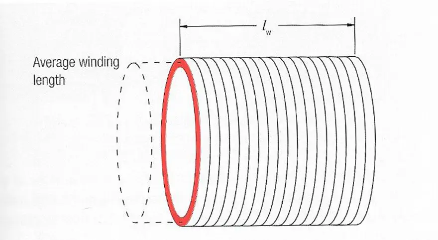
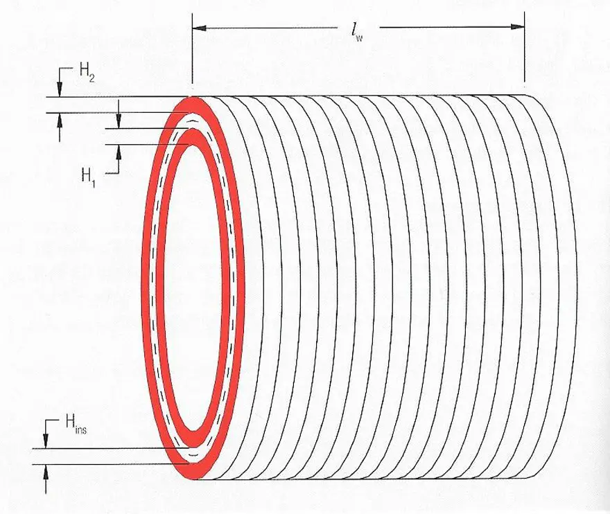
For a long, single‑layer concentric solenoid coil of length , cross‑sectional area , and turns, the self‑inductance can be written asIf a second winding is added on top, the leakage inductance depends on the effective area between the windings. For a long concentric structure the relevant area is
or, more generally, a function of mean length of turn (MLT), insulation thickness , and the winding heights .
Design implications:
- Leakage inductance is independent of core material and air gap; it is governed mainly by winding geometry.
- To reduce leakage inductance, you must either increase the effective winding length (broad windings) or decrease the distance between windings (e.g. bifilar or sandwich structures).
Coupling and winding capacitances
Two main parasitic capacitances affect high‑frequency behaviour:
- Coupling capacitance between windings can be modeled as a plate capacitor whose plates are the facing copper layers. Increasing the distance or reducing overlap area reduces this capacitance, but both actions tend to increase leakage inductance.
- Winding capacitance within one winding arises from turns at different potentials separated by insulation. It increases with the number of layers and can be reduced using techniques such as Z‑winding (wire returned after each layer) or sectioned windings.
These parasitics strongly influence resonances, common‑mode noise, surge behaviour, and the achievable bandwidth of current or voltage transformers, and should therefore be included in accurate models and simulations.
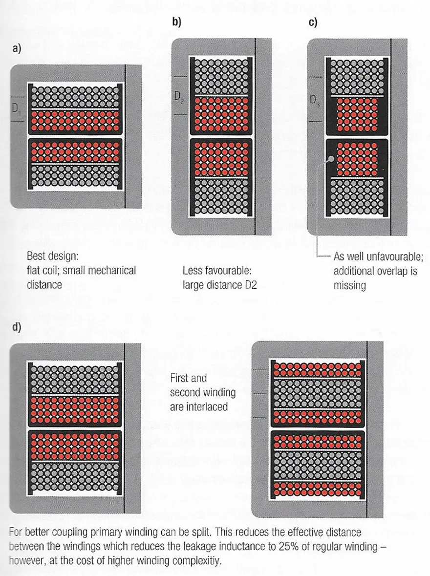
Practical winding structures
Figure‑type examples often used in practice (concentric, split‑primary, sandwich, etc.) trade off leakage inductance against coupling capacitance for a given geometry. A typical improvement is a sandwich construction, where the secondary is wound between two primary halves, effectively doubling the winding length and improving coupling without shrinking creepage distances below safety requirements.
For design engineers, the recommended workflow is:
- Start from electrical requirements (turns ratio, volt‑seconds, flux density, temperature rise, insulation class).
- Choose core material and size, then iterate winding structure (concentric, split, sandwich, interleaved) to meet leakage, capacitance, and EMI constraints.
- Validate with parasitic‑aware models (e.g. physical transformer model in SPICE) and correlate with measurements.
Deep Inside References
For deep inside about transformer see also articles and videos:
Solenoids
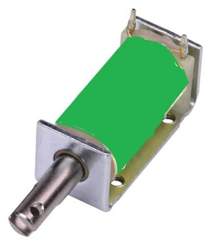
Derived from two Greek words: Solen (pipe) and Eidos (coil), the solenoid is a type of an electromagnetic device that converts electrical energy into mechanical energy. It is generally made by tightly wounding wires in a helix shape around a piece of metal. Whenever an electric current passes through it, a magnetic field is created.
Working Principle
A solenoid works on electromagnetism and electromagnetic force. It consists of a round cylindrical coil that has several number of wire turns, and a metal rod inside the coil that is free to move. When an electric current is provided to the coil, a magnetic field is generated due to which the metal core or rod inside the coil gets attracted due to towards the direction where the magnetic flux is high. This electromagnetic effect in a solenoid enables any connected plunger or armature to move as per our need.
To increase the magnetic force produced in a solenoid coil, we will have to increase the number of turns, N and the current, I.
Types Of Solenoid
AC Laminated Solenoid
It has a very high initial attracting force and very short closing time. It is made with a laminated metal or insulated thin sheets that are individually ,assembled.
DC-C Frame Solenoid
As its name states, this solenoid is constructed in such a way that it has a letter ‘C’ like frame cover around the coil. This type is widely used in gaming machines.
DC-D Frame Solenoid
As its name says, this solenoid has a coil that is covered by two ‘D’ frames on two sides. This types is generally used in AC power applications.
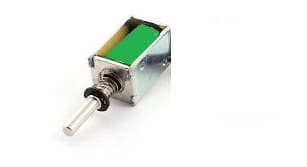
Linear Solenoid
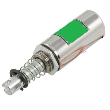
This type of solenoid has a freely movable steel or iron rod called plunger inside a round cylindrical shaped coil. The iron rod is allowed to freely move in or out of the cylindrical coil depending on the current applied.
Rotary Solenoid
It is a special type of solenoid where the magnetic force is converted into a rotational force or a rotary motion. It consists of an armature core mounted on a flat disk.
When a current is provided, the armature gets attracted towards the stator and the flat disk rotates.
Applications
Solenoid Valve
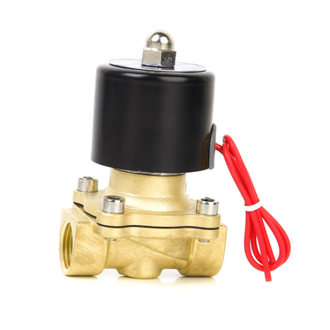
The solenoid valve is a simple device in which a solenoid is used for controlling and regulating the flow of fluid. It has a coil with free movable plunger or an iron rod with a spring inside it. When we energise the coil, the plunger moves from its position due to magnetic attraction and when we cut the power to coil, the plunger comes back to its original position with the help of a spring. As soon as the plunger comes in the path of the flowing fluid, its flow stops.
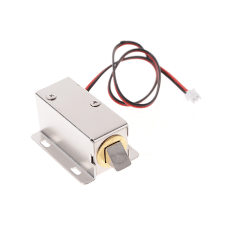
Solenoid Lock
Here we use the movement of solenoid plunger for the locking and unlocking mechanism. These solenoid locks are widely used in electronic and biometric password-based locks. It consists of a strong metal plunger that can move. When the coil gets magnetised due to an electric field, the plunger moves to perform the lock and unlock mechanism.
The leakage inductance is thus independent of core material and air gap. To minimize leakage inductance you must either increase the length of the coil (broad windings) or reduce the distance between the windings (e.g. bifilar wind).
Figure 7. shows various more or less ideal winding constructions. With existing geometry the most commonly used means is a sandwich construction (Figure 7.d), in which the secondary winding is wound between the primary winding that is divided into two halves. This doubles the length of the winding.
Summary
Transformers and solenoids are key inductive components that exploit the same underlying electromagnetic principles but serve different roles in electronic systems. Transformers use magnetic coupling between windings to transfer energy between circuits, setting voltage, current, and impedance levels while their real‑world behavior is strongly influenced by magnetizing current, leakage inductance, and parasitic capacitances.
Solenoids, in contrast, convert electrical energy into controlled linear or rotary motion, with force determined mainly by current, number of turns, and mechanical construction. For design engineers, careful attention to core material, winding geometry, and parasitic effects is essential to optimize efficiency, EMC performance, and reliability in applications ranging from power supplies to actuators and valves.
Frequently Asked Questions about Transformers and Solenoids
A transformer is an electromagnetic device that transfers electric energy from one alternating‑current circuit to another via magnetic coupling between primary and secondary windings, usually stepping voltage up or down while conserving power in the ideal case.
An ideal transformer operates according to the turns ratio between its windings: the voltage ratio equals the turns ratio, and the current ratio is inversely proportional, with magnetizing current being the only current when the secondary is open.
Magnetizing current is the portion of primary current required to establish the magnetic flux in the core; it does not deliver power to the load, so minimizing it through appropriate core material and operating frequency is crucial for good efficiency and regulation.
Leakage inductance represents the part of the magnetic flux from a winding that does not couple to the other winding and appears as a series inductance determined mainly by winding geometry rather than core material or air gap.
Coupling capacitance is the capacitance between primary and secondary windings, while winding capacitance is the capacitance between turns within a winding; both parasitics influence resonances, common‑mode noise, and high‑frequency behaviour.
Careful selection of concentric, split‑primary, or sandwich structures, together with optimized distances and overlap between windings, allows designers to trade leakage inductance against coupling capacitance to meet EMC and performance targets.
A solenoid is a coil‑based electromagnetic device that converts electrical energy into linear or rotary mechanical motion, typically using a movable iron or steel plunger inside a cylindrical coil.
Solenoids are widely used in applications such as solenoid valves for fluid control, locking mechanisms in electronic and biometric locks, and actuators in automation and gaming machines.
The magnetic force of a solenoid increases primarily with higher coil current, a larger number of turns, and suitable magnetic core material and geometry that concentrate the magnetic field around the plunger.
esign engineers must consider core material, winding geometry, parasitic inductances and capacitances, operating frequency, thermal limits, and mechanical requirements to achieve reliable, efficient, and EMC‑compliant designs.
How to Design a Basic Power Transformer
- Define electrical requirements
Start by specifying input and output voltages, frequency, power level, insulation class, temperature rise limits, and any safety or EMC standards that the transformer must meet.
- Select core material and size
Choose a suitable core material (for example ferrite for high‑frequency switch‑mode supplies or laminated steel for mains frequency) and size it for acceptable flux density, losses, and thermal performance.
- Determine turns and turns ratio
Calculate primary and secondary turns from the required volt‑seconds, core cross‑section, and maximum flux density, ensuring that the turns ratio matches the desired voltage transformation.
- Choose winding wire and insulation
Select wire gauge based on allowable current density and temperature rise, then choose insulation systems and bobbins that satisfy creepage, clearance, and dielectric strength requirements.
- Optimize winding geometry
Arrange primary and secondary windings (for example concentric, split‑primary, or sandwich structures) to minimize leakage inductance and control coupling capacitance while maintaining safety distances.
- Model parasitic elements
Include magnetizing inductance, leakage inductances, and inter‑winding and intra‑winding capacitances in a circuit model to predict resonances, transient behaviour, and EMI performance.
- Prototype and measure key parameters
Build a prototype transformer and measure parameters such as magnetizing current, leakage inductance, winding resistance, capacitances, temperature rise, and efficiency under realistic operating conditions.
- Iterate for performance and compliance
Refine core choice, turns counts, and winding layout based on measurement results to meet efficiency, thermal, and EMC specifications, and verify compliance with relevant safety standards.


