



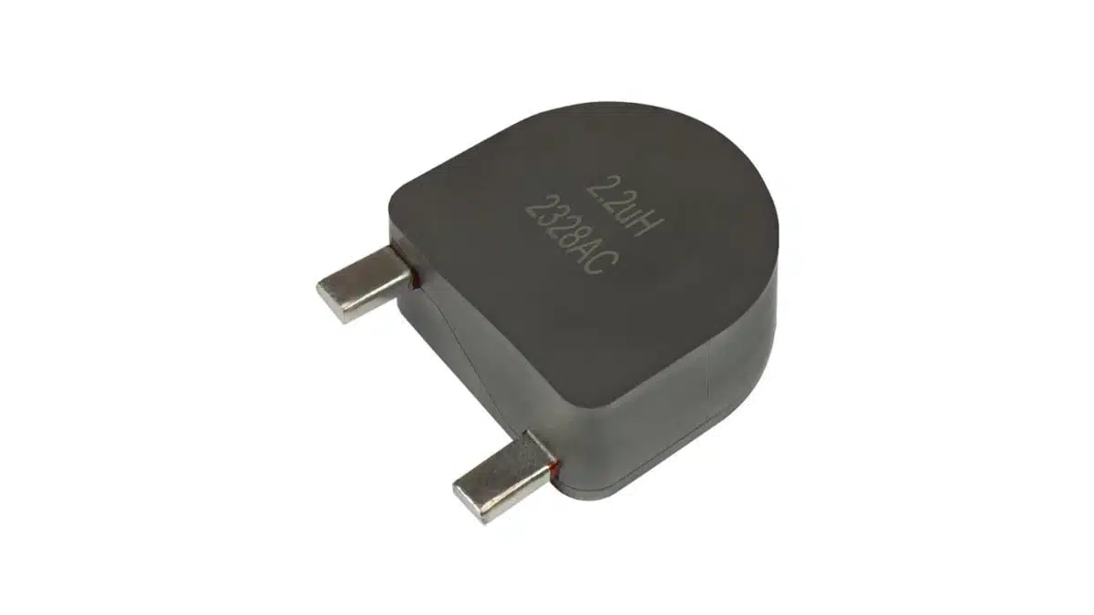
Vishay has expanded its IHXL family of radial through‑hole power inductors with four new high‑current parts targeting demanding automotive and industrial power electronics.
These Vishay high current inductors combine very high rated current up to 209 A with improved core losses and tight EMC control, making them attractive for input filters, PFC chokes, and DC‑link stages in compact, thermally stressed designs.
Introduction
The new IHXL1500VZ-3A, IHXL1500VZ-31, IHXL-2000VZ-3A, and IHXL-2000VZ-31 inductors use a new iron alloy core material and a pressed powdered iron construction in radial THD packages.
Compared to earlier IHXL generations, they offer around 20% lower core losses and support operation up to 155 °C, which directly benefits efficiency and lifetime in high‑power converters. With inductance values up to 10 µH and rated currents up to 209 A, they are suited to high‑ripple environments where stable inductance and controlled EMI are critical.
Key features and benefits
Core and construction
- New iron alloy core with approximately 20% lower core losses than previous IHXL devices, helping reduce converter losses and inductor self‑heating at high ripple currents.
- Pressed powdered iron body that magnetically shields the internal winding, containing stray flux and significantly reducing coupling into neighboring components compared to open wirewound chokes.
- Soft saturation behavior, meaning inductance drops gradually rather than collapsing under transient overload, which improves robustness during inrush and fault conditions.
- Low internal thermal resistance thanks to the solid body construction, lowering hotspot temperatures and improving the effectiveness of forced‑air or conduction cooling.
- Flat top surface designed to simplify attachment of external heatsinks or thermal interface materials when additional cooling is required.
Electrical performance
- High current capability with thick internal copper conductors supporting typical heat‑rating currents from about 55 A up to 209 A, depending on inductance and case size.
- High saturation currents up to several hundred amperes (typical values up to 349 A depending on device and inductance), giving margin against overload and transient spikes.
- Inductance range up to 10 µH, enabling both input filters and DC‑link smoothing where higher impedance and ripple current control are needed.
- Self‑resonant frequency (SRF) in the several‑MHz range (approximately 5.1 MHz to 37.8 MHz typical depending on part and value), which is important when placing the inductor in EMI filters and high‑frequency stages.
Mechanical and qualification aspects
- Automotive Grade variants (IHXL1500VZ-3A and IHXL-2000VZ-3A) qualified to AEC‑Q200 for use in automotive and other harsh environments.
- High operating temperature up to 155 °C, supporting under‑the‑hood and high‑density power modules.
- Robust environmental performance, including high resistance to thermal shock, moisture, and mechanical shock, suitable for long‑life industrial and transportation equipment.
- Customization options for terminations, inductance values, and current, temperature, or voltage ratings if the standard portfolio does not match a particular design constraint.
Typical applications
The combination of high current capability, controlled EMC behavior, and high temperature rating targets a broad set of power electronics use cases.
- High‑current input filters in on‑board and off‑board battery chargers for electric and hybrid vehicles. The shielded construction helps meet conducted and radiated emission limits while handling high DC bias.
- Differential‑mode and boost PFC chokes in AC‑DC front ends where high ripple current and stringent power factor / THD requirements coexist.
- DC‑link filtering in high‑power DC‑DC converters in automotive, industrial, and renewable energy systems, where low ripple and stable inductance over load are important.
- Current smoothing in brushless DC motor drives for automotive (for example, pumps, fans, traction auxiliaries) and industrial motion control, improving torque ripple and reducing EMI.
- Filters in solar and wind inverters, including DC side and grid‑interface stages, where extended temperature range and long‑term reliability are needed.
In many of these applications, the IHXL devices are attractive drop‑in options when designers need to improve EMC margins or thermal headroom without a complete PCB redesign.
Technical highlights
The four new inductors cover two case sizes and both automotive and commercial variants. The table below summarizes the key points extracted from the manufacturer’s device specification table.
IHXL device overview
| Series | Grade | Case size | Dimensions (mm) | Inductance range (µH) | AEC‑Q200 |
|---|---|---|---|---|---|
| IHXL1500VZ-3A | Automotive | 1500 | 38.1 × 38.1 × 21.89 | 0.68 to 10 | Yes |
| IHXL1500VZ-31 | Commercial | 1500 | 38.1 × 38.1 × 21.89 | 1.2 to 10 | No |
| IHXL2000VZ-3A | Automotive | 2000 | 50.8 × 50.8 × 21.7 | 0.68 to 10 | Yes |
| IHXL2000VZ-31 | Commercial | 2000 | 50.8 × 50.8 × 21.7 | 1.2 to 10 | No |
Values according to the manufacturer press release and associated product pages.
Current ratings and resistance
The IHXL1500 and IHXL2000 families provide a range of DCR and current ratings depending on inductance value. Two current definitions are important for design‑in:
- Heat‑rating current: DC current that causes an approximate temperature rise of 40 °C or 80 °C, indicating thermal limits in real operation.
- Saturation current: DC current at which the inductance drops by approximately 20% or 30%, indicating the onset of significant core saturation.
In practice, many designs choose nominal operating current significantly below both limits to ensure margin for ambient variation, airflow changes, and transient overloads. The typical ranges quoted for the new IHXL parts are approximately:
- Heat‑rating currents from about 55 A up to 209 A for a single device, with higher figures given for the larger case and lower inductance values.
- Saturation currents ranging roughly from 49 A up to 349 A, again depending on size and inductance.
Typical DC resistance values range from about 0.12 mΩ up to around 1.10 mΩ (typical), with corresponding maximums slightly higher, which must be checked in the detailed datasheet for the chosen inductance value.
EMC and self‑resonant behavior
Self‑resonant frequency (SRF) values span from roughly 5.1 MHz to 37.8 MHz in the portfolio, depending on case size and inductance. For input filters and PFC chokes this means the inductor remains inductive in the frequency band of interest, while beyond SRF its impedance becomes more capacitive and less useful as an inductor. The magnetically shielded pressed powder construction contributes to better EMC behavior than open coil or toroidal inductors by confining the magnetic field largely within the component body.
Design‑in notes for engineers
Selecting the right variant
- Use the Automotive Grade IHXL1500VZ-3A and IHXL-2000VZ-3A when AEC‑Q200 qualification or compliance with automotive quality systems is a requirement, or when the application faces severe thermal and mechanical stress.
- Use the commercial IHXL1500VZ-31 and IHXL-2000VZ-31 for industrial and renewable energy systems that do not mandate automotive screening but still need high current and extended temperature range.
- Choose between 1500 and 2000 case sizes based on available PCB area, required current rating, and allowed temperature rise; the larger 2000 package offers higher current capability at the expense of footprint.
Thermal design and derating
- Base thermal calculations on the specified heat‑rating current at 40 °C and 80 °C temperature rise, and apply additional derating for high ambient temperatures or restricted airflow as defined in the datasheet.
- Consider using the flat top surface for direct heatsink mounting or to attach thermal pads to a system‑level cold plate, especially in compact power modules where inductor temperature is a limiting factor.
- Pay close attention to PCB copper area, via density, and airflow around the inductor to make full use of the low internal thermal resistance of the pressed powder body.
EMC and layout considerations
- Take advantage of the magnetically shielded construction by placing the inductor closer to sensitive circuits than would be possible with open‑magnetic‑field chokes, but still follow standard practices for keeping noisy nodes and loops compact.
- Use the provided SRF and impedance characteristics to ensure that the inductor remains effective over the conducted EMI frequency range relevant for the target standard (for example, CISPR or automotive OEM limits).
- In differential‑mode filters, verify that the selected inductance and DCR do not compromise efficiency or dynamic response while still meeting attenuation targets.
Current rating and saturation margin
- For high‑reliability designs, select the inductance and current rating such that normal operating current remains comfortably below the 20% inductance‑drop saturation current, leaving headroom for short‑term transients.
- In motor drive and PFC applications with large current ripple, use the specified inductance range and DCR to simulate worst‑case current and temperature rise across the full operating envelope.
- Where extremely high fault currents are possible, the soft saturation behavior can help avoid abrupt inductance collapse, but coordination with upstream protection (fuses, circuit breakers, or semiconductor protection) remains essential.
Qualification, standards, and customization
- For automotive projects, ensure that the chosen IHXL‑3A part supports the required grade and that additional OEM‑specific qualification steps (for example, PPAP) are considered early in the project.
- For non‑standard mechanical constraints or attachment methods, discuss custom termination styles with Vishay, as the series is offered with a degree of customization in terminations and ratings.
- Always confirm final inductance, current, and resistance values, as well as any special screening options, against the latest manufacturer datasheet and product page information.
Source
This article is based on information published by Vishay Intertechnology in its official press release announcing the new IHXL series radial through‑hole inductors and the associated product documentation on the manufacturer’s website.