Passive Components Blog
No Result
View All Result
  • Home
  • NewsFilter
    • All
    • Aerospace & Defence
    • Antenna
    • Applications
    • Automotive
    • Capacitors
    • Circuit Protection Devices
    • electro-mechanical news
    • Filters
    • Fuses
    • Inductors
    • Industrial
    • Integrated Passives
    • inter-connect news
    • Market & Supply Chain
    • Market Insights
    • Medical
    • Modelling and Simulation
    • New Materials & Supply
    • New Technologies
    • Non-linear Passives
    • Oscillators
    • Passive Sensors News
    • Resistors
    • RF & Microwave
    • Telecommunication
    • Weekly Digest

    Overvoltage and Transient Protection for DC/DC Power Modules

    Choosing the Right Capacitor: The Importance of Accurate Measurements

    Littelfuse Releases TMR Switches with Ultra-Low Power Magnetic Sensing

    Skeleton Opens SuperBattery Factory in Finland 

    Kyocera Releases Ultra-Compact Low Voltage Clock Oscillators

    Murata Expands High Rel NTC Thermistors in Compact 0603M Size

    RF Inductors: Selection and Design Challenges for High-Frequency Circuits

    Wk 45 Electronics Supply Chain Digest

    Transformer Safety IEC 61558 Standard

    Trending Tags

    • Ripple Current
    • RF
    • Leakage Current
    • Tantalum vs Ceramic
    • Snubber
    • Low ESR
    • Feedthrough
    • Derating
    • Dielectric Constant
    • New Products
    • Market Reports
  • VideoFilter
    • All
    • Antenna videos
    • Capacitor videos
    • Circuit Protection Video
    • Filter videos
    • Fuse videos
    • Inductor videos
    • Inter-Connect Video
    • Non-linear passives videos
    • Oscillator videos
    • Passive sensors videos
    • Resistor videos

    Choosing the Right Capacitor: The Importance of Accurate Measurements

    RF Inductors: Selection and Design Challenges for High-Frequency Circuits

    Transformer Safety IEC 61558 Standard

    3-Phase EMI Filter Design, Simulation, Calculation and Test

    Transformer Design Optimization for Power Electronics Applications

    Common Mode Chokes Selection for RF Circuits in Next-Generation Communication Systems

    Capacitor Self-balancing in a Flying-Capacitor Buck Converter

    How to Select Ferrite Bead for Filtering in Buck Boost Converter

    Power Inductors Future: Minimal Losses and Compact Designs

    Trending Tags

    • Capacitors explained
    • Inductors explained
    • Resistors explained
    • Filters explained
    • Application Video Guidelines
    • EMC
    • New Products
    • Ripple Current
    • Simulation
    • Tantalum vs Ceramic
  • Knowledge Blog
  • Suppliers
    • Who is Who
  • PCNS
    • PCNS 2025
    • PCNS 2023
    • PCNS 2021
    • PCNS 2019
    • PCNS 2017
  • Events
No Result
View All Result
Passive Components Blog
No Result
View All Result

Lumped Element L-C Filters Design and Characteristics

4.1.2023
Reading Time: 3 mins read
A A

This blog post originated from Knowles Precision Devices, explores the basics of lumped element filter design, general lumped element filter characteristics, and how lumped element filter designs limits can be customized to develop a wide variety of high-performance low-frequency filtering options.

The Basics of Lumped Element L-C Filter Construction

In general, lumped element filters are passive filters constructed using the appropriate number of inductors (Ls), capacitors (Cs), and resistors (Rs) to meet the specific filtering needs of a particular application.

RelatedPosts

3-Phase EMI Filter Design, Simulation, Calculation and Test

Knowles Releases High Q Non-Magnetic X7R MLCCs for Medical Imaging

Knowles Unveils High-Performance Safety-Certified MLCC Capacitors

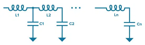
At the most basic level, lumped element filters can be constructed from a collection of simple L-C resonators as shown in Figure 1.

The resonators used in the filter will create poles and zeros in the frequency response. A zero occurs when the function tends to zero, and a pole occurs when the roots that make the function tend towards its maximum function.

By understanding how poles and zeros function (which you can learn more about in this post), we can construct resonators using Ls and Cs and place the poles and zeros where we need them to be to tightly control the frequency response.

Figure 1. An example of a generic lumped element L-C filter structure

Lumped Element Filter Characteristics

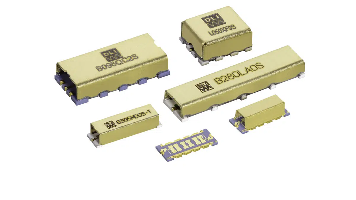
Lumped element filters offer small size at low frequencies that are not achievable with common ceramic, cavity, or waveguide implementations. Additionally, lumped element filter designs are highly customizable both in terms of electrical performance and mechanical and thermal characteristics.

This is because we have a high level of control in terms of component and material choices as well as assembly techniques. For example, a lumped element filter can be constructed with withstand temperature and input power ranges that may not be possible with alternative resonator technologies.

What Filter Types Can Be Built Using a Lumped Element Construction?

All the usual filter types can be implemented in in a lumped element format including lowpass, high pass, bandpass, and band reject. As discussed in more detail in Basic Filter Circuits Explained article, lowpass and high pass elements are relatively simple to develop and bypass filters can be pretty easily constructed by combining the two behaviors.

Lumped Element Filters Capabilities

Lumped element filter frequency and bandwidth range available by Knowles Precision Devices are shown in Figure 2 below.

Figure 2. Lumped element filters frequency and bandwidth range; source: Knowles Precision Devices

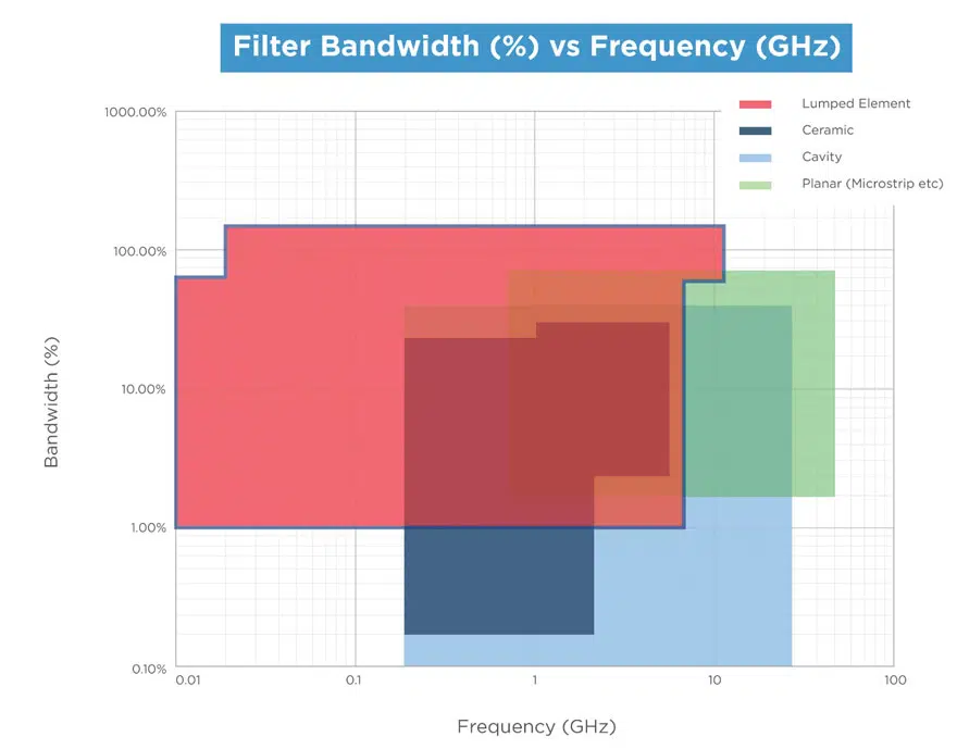
Lumped element filters can be customized to operate reliably in high-power, high-temperature, and harsh environmental conditions. More specifically, lumped element filters can be designed with the following specifications:

  • Bandpass filters with narrow to moderate bandwidths (1 percent FBW to 70 percent FBW) and a Center Frequency (Fo) from 10 MHz to 7 GHz
  • Bandpass filters with an extra wide bandpass bandwidth (70 percent FBW to 175 percent FBW) and a Fo of 20 MHz to 11 GHz
  • Lowpass filters from 10 MHz to 22 GHz
  • Highpass filters from 10 MHz to 10 GHz
  • Bandreject filters from 20 MHz to 6 GHz that can be narrow band or wide band from 10 MHz to 6 GHz

Related

Source: Knowles Precision Devices

Recent Posts

Overvoltage and Transient Protection for DC/DC Power Modules

13.11.2025
21

Choosing the Right Capacitor: The Importance of Accurate Measurements

12.11.2025
37

RF Inductors: Selection and Design Challenges for High-Frequency Circuits

10.11.2025
49

Transformer Safety IEC 61558 Standard

7.11.2025
27

ESR of Capacitors, Measurements and Applications

7.11.2025
95

3-Phase EMI Filter Design, Simulation, Calculation and Test

6.11.2025
77
Image credit: Samtec

How to Match the Right Connector with Protocol Requirements

6.11.2025
20

Transformer Design Optimization for Power Electronics Applications

4.11.2025
26

Microhardness — the Hidden Key to Understanding MnOx Cathode Quality in Tantalum Capacitors

3.11.2025
31

Upcoming Events

Dec 2
December 2 @ 12:00 - December 4 @ 14:15 CET

Microwave Packaging Technology

Dec 9
December 9 @ 12:00 - December 11 @ 14:15 EST

Space and Military Standards for Hybrids and RF Microwave Modules

Dec 10
16:00 - 17:00 CET

Designing Qi2 Wireless Power Systems: Practical Development and EMC Optimization

View Calendar

Popular Posts

  • Buck Converter Design and Calculation

    0 shares
    Share 0 Tweet 0
  • Boost Converter Design and Calculation

    0 shares
    Share 0 Tweet 0
  • Flyback Converter Design and Calculation

    0 shares
    Share 0 Tweet 0
  • LLC Resonant Converter Design and Calculation

    0 shares
    Share 0 Tweet 0
  • Ripple Current and its Effects on the Performance of Capacitors

    3 shares
    Share 3 Tweet 0
  • MLCC and Ceramic Capacitors

    0 shares
    Share 0 Tweet 0
  • Dual Active Bridge (DAB) Topology

    0 shares
    Share 0 Tweet 0
  • What is a Dielectric Constant and DF of Plastic Materials?

    4 shares
    Share 4 Tweet 0
  • SEPIC Converter Design and Calculation

    0 shares
    Share 0 Tweet 0
  • What Electronics Engineer Needs to Know About Passive Low Pass Filters

    0 shares
    Share 0 Tweet 0

Newsletter Subscription


Passive Components Blog

© EPCI - Leading Passive Components Educational and Information Site

  • Home
  • Privacy Policy
  • EPCI Membership & Advertisement
  • About

No Result
View All Result
  • Home
  • Knowledge Blog
  • PCNS

© EPCI - Leading Passive Components Educational and Information Site

This website uses cookies. By continuing to use this website you are giving consent to cookies being used. Visit our Privacy and Cookie Policy.
Go to mobile version