Source: Electronics 360 article
Traditional, discrete, passive RF filters are following the trend of digital circuits, becoming smaller in size and more integrated into a package. New material processes like multi-layer organic (MLO) and embedded substrate techniques have enabled this trend.
Miniaturization
Like their digital brethren, RF and microwave passive components have followed the trend toward shrinking package sizes, increased component integration and lowered overall cost while improving performance, especially at high frequencies.
Reductions in package size typically have the added benefit of reducing package weight, which is a critical consideration in avionic and space systems. One popular technique to achieve size and weight reduction is to embed passive devices such as capacitors, inductors and resistors into device substrates. Thin film technologies that support embedded fabrication can also improve electronic performance by reducing parasitic impedance.
Electronic component miniaturization is a growing trend in aerospace and defense, consumer communications, homeland security and other applications. In support of this movement, the IEEE professional society has recently created a new journal devoted entirely to the “rapidly evolving field of small air and space systems such as drones and small satellites.” The IEEE Journal on Miniaturization for Air and Space Systems (J-MASS) will debut next year.
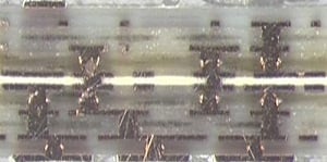
Figure 1. Typical cross-section of an MLO device. Dielectrics and metalized copper are used to construct layers of capacitors and inductors. Source: AVX
To achieve size reductions, filter designers are using new materials and process techniques like MLO to manufacture both capacitive and inductive components (Figure 1).
Material Changes for Filters
Traditional filter solutions are based on discrete ceramic or silicon passive components, both of which can be expensive and difficult to integrate into ever-smaller sizes. Recently, a new type of RF package has emerged, one that is based on laminating multiple layers of organic materials together. This approach, combining thin organic dielectric materials embedded into substrates, has been applied to a variety of RF products, including tightly integrated RF front-end-modules and filters. It has proven to be more effective than other alternatives, such as low temperature co-fired ceramic (LTCC) and conventional laminate substrates, which have difficulty integrating into shrinking sizes and silicon geometries. Further, LTCC is a costly process that has had temperature-related failures with common PCB-type substrate materials, and the components based on LTCC suffer from performance drift with temperature changes. MLO filters offer a superior solution with performance that is consistent across the specified temperature ranges.
In addition to temperature, MLO devices provide significant electrical, physical and reliability advantages over traditional discrete RF or LTCC solutions.
MLO-based capacitors are created using high Q-grade dielectric around which solid copper plates (forming the electrodes) are laminated. The quality, or Q factor, represents a critical parameter for high-frequency filters. Q is equal to the capacitor’s reactance divided by the capacitor’s parasitic resistance.
As in capacitors, MLO-based inductors use thick copper to form the metallization that maximizes the inductor Q. The higher the Q factor of the inductor, the closer it approaches the behavior of an ideal inductor. The higher the Q, the narrower the bandwidth of the resonant (LC) filter circuit.
These MLO-based techniques along with technology to embed devices into substrates have changed the way compact, tightly integrated RF filters are designed.
Specifying a Filter
Specifying an RF filter starts by first understanding the desired function of the filter. What does the filter need to do (e.g., remove noise, pass certain frequencies or reject others)?
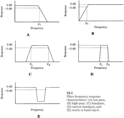
Figure 2. Filters come in four basic types: low-pass, high-pass, band-pass and notch. All of these filters are classified according to the frequencies that they pass or reject. Source: IEEE
GlobalSpecFilters are grouped according to their frequency effect on input signals: low-pass, high-pass, band-pass and band-reject. For example, a low-pass filter helps to remove high-frequency noise and interference by attenuating signals above a cut-off frequency. Conversely, a high-pass filter passes high-frequency signals while removing low-frequency distortions below a specified cutoff frequency. A band-pass filter passes a given band of frequencies, rejecting signals on either side (below and above) of the pass-band. Finally, a band-stop, band-reject or notch filter passes all signals except at a specific frequency and bandwidth around the frequency (Figure 2).
Theoretically, all filters would pass only wanted signals without loss while attenuating all unwanted signals to zero. In the real world, filters don’t meet this ideal performance. Instead, a set of performance parameters must be specified to show how actual filters deviate from the ideal (e.g., pass-band insertion loss, phase response, Q factor and others). As a rule of thumb, high-Q circuit elements provide high-performance in narrow band filter responses while low-Q circuits yield higher pass-band insertion loss and lower stop-band attenuation.
It’s important for engineers to understand the basic types and parameters when specifying a filter. Failure to appreciate filter types and minimum specification requirements can result in poorly performing filters. First and foremost, designers must specify the basic frequency response curves that they want, such as low-pass, high-pass, band-pass and band-stop.
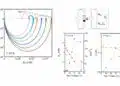
“Customers will tell us the frequency response they need including the insertion loss, roll off, rejection frequencies and how far they want to reject,” explains Edgardo Menendez, principal RF technology marketing engineer at AVX. “For example, insertion loss values in a passband filter can be anywhere from 0.5 dB to 5 dB. The rejected signals need to roll off quickly at specific levels like 20, 30 or 40 dB.”
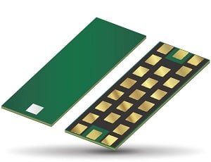
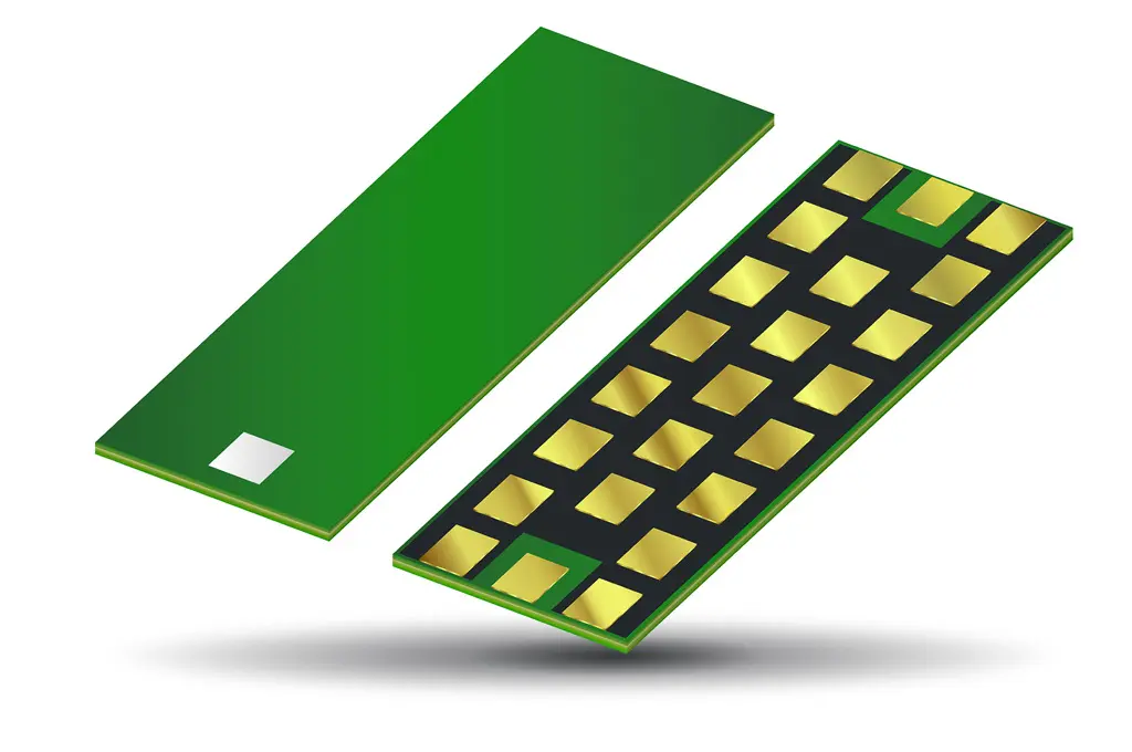
Figure 3. BP series MLO band-pass filters. Source: AVX
If the device size is as important as its electrical specifications, then engineers should consider an MLO filter (Figure 3). As demonstrated at this year’s IEEE IMS event, AVX’s new BP series of MLO, high-performance, band-pass filters provide low insertion losses within wide pass-bands, steep roll-offs and very high rejections of out-of-band frequencies. Size-wise, these filters can be less than 1.0 mm in thickness as well as embedded in substrates.
Summary
The trend toward miniaturization in avionics and other fields has prompted builders of RF and microwave filters to implement new techniques to shrink and tightly integrate passive components. One of the most popular approaches is using reliable, high-performance MLO techniques with embedded passive components. With proper frequency response specifications, MLO devices have proven capable of challenging conventional multi-layer ceramic technology in the future generation of miniaturized filters.