Passive Components Blog
No Result
View All Result
  • Home
  • NewsFilter
    • All
    • Aerospace & Defence
    • Antenna
    • Applications
    • Automotive
    • Capacitors
    • Circuit Protection Devices
    • electro-mechanical news
    • Filters
    • Fuses
    • Inductors
    • Industrial
    • Integrated Passives
    • inter-connect news
    • Market & Supply Chain
    • Market Insights
    • Medical
    • Modelling and Simulation
    • New Materials & Supply
    • New Technologies
    • Non-linear Passives
    • Oscillators
    • Passive Sensors News
    • Resistors
    • RF & Microwave
    • Telecommunication
    • Weekly Digest

    Researchers Enhanced 2D Ferromagnets Performance

    Bourns Releases Two High Current Common Mode Choke Models

    Electronics Weekly Announcing Finalists for Elektra Awards 2025

    Exxelia Exhibit at Electronica India September 17–19, 2025

    Würth Elektronik Announces 2025 Digital WE Days Virtual Conference

    VINATech Unveils Hybrid Energy Storage System to Revolutionize Grid Stability and Power Delivery

    SCHURTER Releases High Performance EV-Fuse

    Panasonic Industry to Double Production of MEGTRON PCB Materials

    5th PCNS Awards Outstanding Passive Component Papers

    Trending Tags

    • Ripple Current
    • RF
    • Leakage Current
    • Tantalum vs Ceramic
    • Snubber
    • Low ESR
    • Feedthrough
    • Derating
    • Dielectric Constant
    • New Products
    • Market Reports
  • VideoFilter
    • All
    • Antenna videos
    • Capacitor videos
    • Circuit Protection Video
    • Filter videos
    • Fuse videos
    • Inductor videos
    • Inter-Connect Video
    • Non-linear passives videos
    • Oscillator videos
    • Passive sensors videos
    • Resistor videos

    Ripple Steering in Coupled Inductors: SEPIC Case

    SEPIC Converter with Coupled and Uncoupled Inductors

    Coupled Inductors in SEPIC versus Flyback Converters

    Non-Linear MLCC Class II Capacitor Measurements Challenges

    Percolation Phenomenon and Reliability of Molded Power Inductors in DC/DC converters

    Root Causes and Effects of DC Bias and AC in Ceramic Capacitors

    How to Calculate the Output Capacitor for a Switching Power Supply

    Switched Capacitor Converter Explained

    Understanding Inductor Dot Markings and Their Application in LTspice

    Trending Tags

    • Capacitors explained
    • Inductors explained
    • Resistors explained
    • Filters explained
    • Application Video Guidelines
    • EMC
    • New Products
    • Ripple Current
    • Simulation
    • Tantalum vs Ceramic
  • Knowledge Blog
  • Suppliers
    • Who is Who
  • Events
No Result
View All Result
Passive Components Blog
No Result
View All Result

Murata adds to lineup of lead type multilayer ceramic capacitors for automotive use at 175°C/200°C

11.1.2018
Reading Time: 3 mins read
A A

source: Murata news

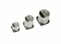
Murata Manufacturing Co., Ltd. has expanded the RHS Series of lead type multilayer ceramic capacitors for automotive use in high temperature applications. Products newly introduced at this time include a 100Vdc rated product for 200°C use, which expands the previous lineup of 200Vdc and 500Vdc products, and a 100Vdc rated product for 175°C use with high capacitance. These products are primarily meant for use in equipment located in severe temperature environments such as the engine compartment of an automobile. The 100Vdc rated product for 200°C will begin mass production at Iwami Murata Manufacturing Co., Ltd. in January 2018, and the 100Vdc rated product for 175°C will begin in February 2018. Samples are available for ¥200. 
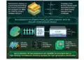
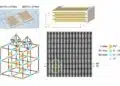
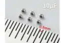
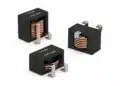
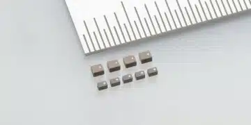
A power train control system uses a DC motor drive to increase control in order to improve the fuel economy of an automobile. A capacitor is used to suppress the electrical noise generated by this DC motor. The automobile control equipment is mounted in an extreme environment, where temperatures can approach 200°C for short periods of time. A high degree of durability is needed for a capacitor that is implemented in this environment. This series from Murata applies a coating of newly developed heat resistant resin around a highly heat resistant multilayer ceramic capacitor, allowing use at a 200°C maximum temperature. The previous products with rated voltage of 200Vdc and 500Vdc had capacitance of 0.01μF, but the newly added 100Vdc product for 175°C and 200°C offers a smaller size and expands capacitance up to 0.1µF. The company expects to expand sales of products for equipment mounted in high temperature environments such as engine compartments.

RelatedPosts

Researchers Enhanced 2D Ferromagnets Performance

Bourns Releases Two High Current Common Mode Choke Models

Electronics Weekly Announcing Finalists for Elektra Awards 2025

Features

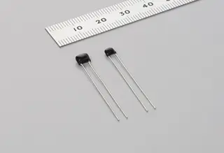
  • Lead wire type capacitor can be connected by welding or “crimping*1” close to a noise generating source.
  • Complies with AEC-Q200*2
  • Passes the extreme surge test of the ISO7637-2*3 standard.

Detailed specification

Operating temperature range -55 to 175°C -55 to 200°C
Rated Voltage
100Vdc
(Rated voltage at 175°C is reduced to 50%)
100Vdc
(temperature characteristics code: 7G)

200Vdc、500Vdc (temperature characteristics code: 7J)

(Rated voltage at 200°C is reduced to 25%)
Capacitance and temperature characteristics
Or
Temperature Coefficient
(ppm/°C)
Temperature characteristics code:L1
-55 to 175°C:+15/-40%
Temperature characteristics code:N1
-55 to 175°C:+15/-60%
Temperature characteristics code:7G
-55 to 25°C  :0 +30/-72ppm/°C
25 to 125°C  :0 +/-30ppm/°C
125 to 200°C:0 +72/-30ppm/°C
Temperature characteristics code:7J
-55 to 25°C  :-750 +120/-347ppm/°C
25 to 125°C  :-750 +/-120ppm/°C
125 to 200°C:-750 +347/-120ppm/°C
Capacitance range

Temperature characteristics code:L1
4700pF to 0.1μF

Temperature characteristics code:N1
4700pF to 0.22μF

Temperature characteristics code:7G
100pF to 3300pF

Temperature characteristics code:7J
100pF to 0.01μF

Dimensions
(L×W)
Size0:3.8×3.5mm max
Size1:4.0×3.5mm max
Size2:5.5×4.0mm max

External dimensions and lead wire pitch

 L×W: Determined by the combination of rated voltage and electrostatic capacity.
 F(lead wire pitch): For 100Vdc and 200Vdc rated products, this can be selected from either 2.5mm or 5.0mm.
For 500Vdc products, this is 5.0mm.

About voltage/temperature derating

When product temperature exceeds 150°C, reduce the voltage to be applied to the capacitor in correlation to the rated voltage shown below.

Explanation of terms

*1. Crimping:A metal component or fitting is fastened using a pliers or custom tool without using an adhesive.

*2. AEC-Q200:Test standards for reliability sought in automobile electrical parts, as decided by the Automotive Electronics Council.

*3. ISO7637-2:Test standards for checking durability against noise generated by automobile electrical equipment.

Related

Recent Posts

Bourns Releases Two High Current Common Mode Choke Models

16.9.2025
1

Electronics Weekly Announcing Finalists for Elektra Awards 2025

16.9.2025
3

Exxelia Exhibit at Electronica India September 17–19, 2025

15.9.2025
22

Würth Elektronik Announces 2025 Digital WE Days Virtual Conference

15.9.2025
10

VINATech Unveils Hybrid Energy Storage System to Revolutionize Grid Stability and Power Delivery

15.9.2025
9

SCHURTER Releases High Performance EV-Fuse

15.9.2025
4

5th PCNS Awards Outstanding Passive Component Papers

14.9.2025
34

TDK Releases Ultra-small PFC Capacitors

10.9.2025
31

KYOCERA AVX Releases Novel Mini BME Stacked Ceramic Capacitors

10.9.2025
25

Vishay Releases Class 1 Leaded High Voltage Ceramic Disc Capacitors

10.9.2025
17

Upcoming Events

Sep 22
September 22 @ 13:00 - September 25 @ 15:15 EDT

Pre Cap Visual Inspection per Mil-Std-883 (TM 2017)

Sep 30
September 30 @ 12:00 - October 2 @ 14:00 EDT

MIL-Std-883 TM 2010

Oct 17
12:00 - 14:00 EDT

External Visual Inspection per MIL-STD-883 TM 2009

Oct 20
October 20 - October 23

Digital WE Days 2025 – Virtual Conference

Oct 21
October 21 @ 12:00 - October 23 @ 14:15 EDT

Space and Military Standards for Hybrids and RF Microwave Modules

View Calendar

Popular Posts

  • Buck Converter Design and Calculation

    0 shares
    Share 0 Tweet 0
  • Boost Converter Design and Calculation

    0 shares
    Share 0 Tweet 0
  • Flyback Converter Design and Calculation

    0 shares
    Share 0 Tweet 0
  • LLC Resonant Converter Design and Calculation

    0 shares
    Share 0 Tweet 0
  • Dual Active Bridge (DAB) Topology Explained

    0 shares
    Share 0 Tweet 0
  • Ripple Current and its Effects on the Performance of Capacitors

    3 shares
    Share 3 Tweet 0
  • What is a Dielectric Constant and DF of Plastic Materials?

    4 shares
    Share 4 Tweet 0
  • SEPIC Converter Design and Calculation

    0 shares
    Share 0 Tweet 0
  • How to Design an Inductor

    0 shares
    Share 0 Tweet 0
  • Core Materials, Permeability and Their Losses

    0 shares
    Share 0 Tweet 0

Newsletter Subscription


Passive Components Blog

© EPCI - Leading Passive Components Educational and Information Site

  • Home
  • Privacy Policy
  • EPCI Membership & Advertisement
  • About

No Result
View All Result
  • Home
  • Knowledge Blog
  • Premium Suppliers

© EPCI - Leading Passive Components Educational and Information Site

This website uses cookies. By continuing to use this website you are giving consent to cookies being used. Visit our Privacy and Cookie Policy.
Go to mobile version