Passive Components Blog
No Result
View All Result
  • Home
  • NewsFilter
    • All
    • Aerospace & Defence
    • Antenna
    • Applications
    • Automotive
    • Capacitors
    • Circuit Protection Devices
    • electro-mechanical news
    • Filters
    • Fuses
    • Inductors
    • Industrial
    • Integrated Passives
    • inter-connect news
    • Market & Supply Chain
    • Market Insights
    • Medical
    • Modelling and Simulation
    • New Materials & Supply
    • New Technologies
    • Non-linear Passives
    • Oscillators
    • Passive Sensors News
    • Resistors
    • RF & Microwave
    • Telecommunication
    • Weekly Digest

    Vishay Releases Industry First Automotive SMD Y1 Safety Ceramic Capacitors

    Researchers Enhanced 2D Ferromagnets Performance

    Bourns Releases Two High Current Common Mode Choke Models

    Electronics Weekly Announcing Finalists for Elektra Awards 2025

    Exxelia Exhibit at Electronica India September 17–19, 2025

    Würth Elektronik Announces 2025 Digital WE Days Virtual Conference

    VINATech Unveils Hybrid Energy Storage System to Revolutionize Grid Stability and Power Delivery

    SCHURTER Releases High Performance EV-Fuse

    Panasonic Industry to Double Production of MEGTRON PCB Materials

    Trending Tags

    • Ripple Current
    • RF
    • Leakage Current
    • Tantalum vs Ceramic
    • Snubber
    • Low ESR
    • Feedthrough
    • Derating
    • Dielectric Constant
    • New Products
    • Market Reports
  • VideoFilter
    • All
    • Antenna videos
    • Capacitor videos
    • Circuit Protection Video
    • Filter videos
    • Fuse videos
    • Inductor videos
    • Inter-Connect Video
    • Non-linear passives videos
    • Oscillator videos
    • Passive sensors videos
    • Resistor videos

    Ripple Steering in Coupled Inductors: SEPIC Case

    SEPIC Converter with Coupled and Uncoupled Inductors

    Coupled Inductors in SEPIC versus Flyback Converters

    Non-Linear MLCC Class II Capacitor Measurements Challenges

    Percolation Phenomenon and Reliability of Molded Power Inductors in DC/DC converters

    Root Causes and Effects of DC Bias and AC in Ceramic Capacitors

    How to Calculate the Output Capacitor for a Switching Power Supply

    Switched Capacitor Converter Explained

    Understanding Inductor Dot Markings and Their Application in LTspice

    Trending Tags

    • Capacitors explained
    • Inductors explained
    • Resistors explained
    • Filters explained
    • Application Video Guidelines
    • EMC
    • New Products
    • Ripple Current
    • Simulation
    • Tantalum vs Ceramic
  • Knowledge Blog
  • Suppliers
    • Who is Who
  • Events
No Result
View All Result
Passive Components Blog
No Result
View All Result

Murata launches surface mount type Y1 class safety certified capacitor

15.5.2017
Reading Time: 2 mins read
A A

source: Murata news

Murata Manufacturing Co., Ltd. has launched a surface mount type IEC 60384-14*1 Y1*2 class safety certified ceramic capacitor for low-profile power supplies. This capacitor is ideal for all AC-DC switching power supplies where a low-profile is sought for compact AV equipment, LED illumination, or 1U*3 rack mounted equipment. The mass production of the capacitor began in May 2017.

RelatedPosts

Vishay Releases Industry First Automotive SMD Y1 Safety Ceramic Capacitors

Researchers Enhanced 2D Ferromagnets Performance

Bourns Releases Two High Current Common Mode Choke Models

Safety certified capacitors are placed at a power line input side in order to eliminate noise that builds up primarily in commercial AC power lines.
Safety certified capacitors are usually of the lead type, but the mounted height above the board surface is a problem because it hinders efforts to make low-profile devices and it limits component layout. In addition, because lead type capacitors are through-hole mounted, the lead wires are exposed on the underside of the circuit board. A fixed amount of insulating distance between the exposed lead wires and the metal components of the device is required by safety standards, so this complicates spatial layout within a device.

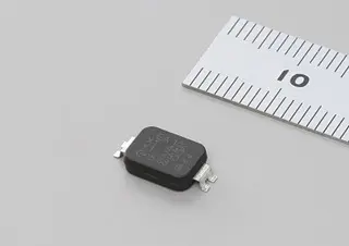
The new Murata capacitor uses a structure of plate-shaped terminals on a disc-shaped ceramic dielectric placed within a plastic mold to reduce the terminal thickness that is present with lead type capacitors, and this results in a mounted height of 2.5mm or less for the product. Furthermore, the component format enables reflow surface mount, and there is no longer a need to assure insulating distance at the underside of the board. This advances profile reduction for power supply devices subject to size limitations in compact AV equipment, LED illumination and 1U rack mounted equipment, for which spatial design has been difficult.

Electrical characteristics

Usage Temperature Range -40℃~125℃
Rated Voltage Y1: AC300V (r.m.s.) or AC250V (r.m.s.)
X1: AC440V (r.m.s.)
Capacitance 10pF ~ 1500pF
Certification Standards
(applied standards)
UL (UL 60384-14)
ENEC (EN 60384-14)
CQC (IEC 60384-14)
KTC (KC 60384-14)

External size

Unit: mm, reference value with ()

L 11.4 +/- 0.5
W 6.0 +/- 0.5
T 2.5 or less

Explanation of terms
*1. IEC 60384-14: An international standard that regulates the withstanding pressure and combustion resistance of capacitors connected to commercial power supplies, from the standpoint of preventing fires and electric shock from electrical leakage.
*2. Y1: A subclass of capacitors classified by insulation type in the standard mentioned above. Y1 subclass capacitors have the highest performance requirements.
*3. 1U: A unit that expresses the height of a device such as a server or storage unit that is stored in a 19 inch rack placed in a data center or other location. A device with a height equivalent to a single stage is said to have height of 1U, and a device with height equivalent to two stages has a height of 2U. The height of 1U is generally held to be “1U = 1.75 inch” by the computer industry related Electronic Industries Alliance (EIA).

Related

Recent Posts

Vishay Releases Industry First Automotive SMD Y1 Safety Ceramic Capacitors

17.9.2025
5

Bourns Releases Two High Current Common Mode Choke Models

16.9.2025
8

Electronics Weekly Announcing Finalists for Elektra Awards 2025

16.9.2025
8

Exxelia Exhibit at Electronica India September 17–19, 2025

15.9.2025
28

Würth Elektronik Announces 2025 Digital WE Days Virtual Conference

15.9.2025
11

VINATech Unveils Hybrid Energy Storage System to Revolutionize Grid Stability and Power Delivery

15.9.2025
18

5th PCNS Awards Outstanding Passive Component Papers

17.9.2025
61

TDK Releases Ultra-small PFC Capacitors

10.9.2025
35

KYOCERA AVX Releases Novel Mini BME Stacked Ceramic Capacitors

10.9.2025
28

Vishay Releases Class 1 Leaded High Voltage Ceramic Disc Capacitors

10.9.2025
23

Upcoming Events

Sep 22
September 22 @ 13:00 - September 25 @ 15:15 EDT

Pre Cap Visual Inspection per Mil-Std-883 (TM 2017)

Sep 30
September 30 @ 12:00 - October 2 @ 14:00 EDT

MIL-Std-883 TM 2010

Oct 17
12:00 - 14:00 EDT

External Visual Inspection per MIL-STD-883 TM 2009

Oct 20
October 20 - October 23

Digital WE Days 2025 – Virtual Conference

Oct 21
October 21 @ 12:00 - October 23 @ 14:15 EDT

Space and Military Standards for Hybrids and RF Microwave Modules

View Calendar

Popular Posts

  • Buck Converter Design and Calculation

    0 shares
    Share 0 Tweet 0
  • Boost Converter Design and Calculation

    0 shares
    Share 0 Tweet 0
  • Flyback Converter Design and Calculation

    0 shares
    Share 0 Tweet 0
  • LLC Resonant Converter Design and Calculation

    0 shares
    Share 0 Tweet 0
  • Dual Active Bridge (DAB) Topology Explained

    0 shares
    Share 0 Tweet 0
  • Ripple Current and its Effects on the Performance of Capacitors

    3 shares
    Share 3 Tweet 0
  • What is a Dielectric Constant and DF of Plastic Materials?

    4 shares
    Share 4 Tweet 0
  • SEPIC Converter Design and Calculation

    0 shares
    Share 0 Tweet 0
  • How to Design an Inductor

    0 shares
    Share 0 Tweet 0
  • Core Materials, Permeability and Their Losses

    0 shares
    Share 0 Tweet 0

Newsletter Subscription


Passive Components Blog

© EPCI - Leading Passive Components Educational and Information Site

  • Home
  • Privacy Policy
  • EPCI Membership & Advertisement
  • About

No Result
View All Result
  • Home
  • Knowledge Blog
  • Premium Suppliers

© EPCI - Leading Passive Components Educational and Information Site

This website uses cookies. By continuing to use this website you are giving consent to cookies being used. Visit our Privacy and Cookie Policy.
Go to mobile version