Passive Components Blog
No Result
View All Result
  • Home
  • NewsFilter
    • All
    • Aerospace & Defence
    • Antenna
    • Applications
    • Automotive
    • Capacitors
    • Circuit Protection Devices
    • electro-mechanical news
    • Filters
    • Fuses
    • Inductors
    • Industrial
    • Integrated Passives
    • inter-connect news
    • Market & Supply Chain
    • Market Insights
    • Medical
    • Modelling and Simulation
    • New Materials & Supply
    • New Technologies
    • Non-linear Passives
    • Oscillators
    • Passive Sensors News
    • Resistors
    • RF & Microwave
    • Telecommunication
    • Weekly Digest

    Murata Christophe Pottier Appointed President of EPCIA

    3-Phase EMI Filter Design, Simulation, Calculation and Test

    YAGEO Unveils Compact 2.4 GHz SMD Antenna

    KYOCERA AVX Releases Antenna for Iridium Satellite IoT Applications

    Molex Releases Industry-First Quad-Row Board-to-Board Connectors with EMI Shields

    Image credit: Samtec

    How to Match the Right Connector with Protocol Requirements

    Smoltek CNF-MIM Capacitors Pass 1,000h Reliability Test

    Capacitor Lead Times: October 2025

    Paumanok Unveils Aluminum Capacitor Foils World Markets Study 2025-2030

    Trending Tags

    • Ripple Current
    • RF
    • Leakage Current
    • Tantalum vs Ceramic
    • Snubber
    • Low ESR
    • Feedthrough
    • Derating
    • Dielectric Constant
    • New Products
    • Market Reports
  • VideoFilter
    • All
    • Antenna videos
    • Capacitor videos
    • Circuit Protection Video
    • Filter videos
    • Fuse videos
    • Inductor videos
    • Inter-Connect Video
    • Non-linear passives videos
    • Oscillator videos
    • Passive sensors videos
    • Resistor videos

    3-Phase EMI Filter Design, Simulation, Calculation and Test

    Transformer Design Optimization for Power Electronics Applications

    Common Mode Chokes Selection for RF Circuits in Next-Generation Communication Systems

    Capacitor Self-balancing in a Flying-Capacitor Buck Converter

    How to Select Ferrite Bead for Filtering in Buck Boost Converter

    Power Inductors Future: Minimal Losses and Compact Designs

    Percolation Phenomenon: Degradation of Molded Power Inductors in DC/DC Converters

    Connector PCB Design Challenges

    Efficient Power Converters: Duty Cycle vs Conduction Losses

    Trending Tags

    • Capacitors explained
    • Inductors explained
    • Resistors explained
    • Filters explained
    • Application Video Guidelines
    • EMC
    • New Products
    • Ripple Current
    • Simulation
    • Tantalum vs Ceramic
  • Knowledge Blog
  • Suppliers
    • Who is Who
  • PCNS
    • PCNS 2025
    • PCNS 2023
    • PCNS 2021
    • PCNS 2019
    • PCNS 2017
  • Events
No Result
View All Result
Passive Components Blog
No Result
View All Result

Researchers expand microchip capability with new 3D inductor technology

24.1.2020
Reading Time: 3 mins read
A A

Smaller is better when it comes to microchips, researchers from said, and by using 3D components on a standardized 2D microchip manufacturing platform, developers can use up to 100 times less chip space. A team of engineers has boosted the performance of its previously developed 3D inductor technology by adding as much as three orders of magnitudes more induction to meet the performance demands of modern electronic devices.

Featured video: A video of the rolling progress of a 1-cm-long microinductor played-back at 10-times speed. The electrical contacts are at the bottom of the device. Reprinted with permission from X. Li et al., Science Advances (2020).

RelatedPosts

Murata Christophe Pottier Appointed President of EPCIA

3-Phase EMI Filter Design, Simulation, Calculation and Test

YAGEO Unveils Compact 2.4 GHz SMD Antenna

In a study led by Xiuling Li, an electrical and computer engineering professor at the University of Illinois and interim director of the Holonyak Micro and Nanotechnology Laboratory, engineers introduce a microchip inductor capable of tens of millitesla-level magnetic induction. Using fully integrated, self-rolling magnetic nanoparticle-filled tubes, the technology ensures a condensed magnetic field distribution and energy storage in 3D space – all while keeping the tiny footprint needed to fit on a chip. The findings of the study are published in the journal Science Advances.  

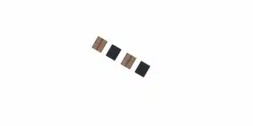
Traditional microchip inductors are relatively large 2D spirals of wire, with each turn of the wire producing stronger inductance. In a previous study, Li’s research group developed 3D inductors using 2D processing by switching to a rolled membrane paradigm, which allows for wire spiraling out of plane and is separated by an insulating thin film from turn to turn. When unrolled, the previous wire membranes were 1 millimeter long but took up 100 times less space than the traditional 2D inductors. The wire membranes reported in this work are 10 times the length at 1 centimeter, allowing for even more turns – and higher inductance – while taking up about the same amount of chip space.

“A longer membrane means more unruly rolling if not controlled,” Li said. “Previously, the self-rolling process was triggered and took place in a liquid solution. However, we found that while working with longer membranes, allowing the process to occur in a vapor phase gave us much better control to form tighter, more even rolls.”

Another key development in the new microchip inductors is the addition of a solid iron core. “The most efficient inductors are typically an iron core wrapped with metal wire, which works well in electronic circuits where size is not as important of a consideration,” Li said. “But that does not work at the microchip level, nor is it conducive to the self-rolling process, so we needed to find a different way.”

To do this, the researchers filled the already-rolled membranes with an iron oxide nanoparticle solution using a tiny dropper.

“We take advantage of capillary pressure, which sucks droplets of the solution into the cores,” Li said. “The solution dries, leaving iron deposited inside the tube. This adds properties that are favorable compared to industry-standard solid cores, allowing these devices to operate at higher frequency with less performance loss.”

Though a significant advance on earlier technology, the new microchip inductors still have a variety of issues that the team is addressing, Li said.

“As with any miniaturized electronic device, the grand challenge is heat dissipation,” she said. “We are addressing this by working with collaborators to find materials that are better at dissipating the heat generated during induction. If properly addressed, the magnetic induction of these devices could be as large as hundreds to thousands of millitesla, making them useful in a wide range of applications including power electronics, magnetic resonance imaging and communications.”

Researchers from Stanford University, Hefei University of Technology, China, and the University of Twente, The Netherlands also participated in this study.

Li also is affiliated with the department of mechanical science and engineering, the Materials Research Laboratory and the Beckman Institute for Advanced Science and Technology at the U. of I.

The National Science Foundation Engineering Research Center for Power Optimization of Electro-Thermal Systems and the U.S. Department of Energy supported this research.

The paper “Monolithic mtesla-level magnetic induction by self-rolled-up membrane technology” is available online and from the U. of I. News Bureau. DOI: 10.1126/sciadv.aay4508

Related

Source: Illinois News Bureau

Recent Posts

3-Phase EMI Filter Design, Simulation, Calculation and Test

6.11.2025
17

Coilcraft Introduces Ultra-Low Loss Shielded Power Inductors

6.11.2025
6

Exxelia Presents Smart Integrated Magnetics Solution at Space Tech Expo 2025 

5.11.2025
14

Murata Expands High Cutoff Frequency Chip Common Mode Chokes

5.11.2025
8

Transformer Design Optimization for Power Electronics Applications

4.11.2025
13

Lightweight Model for MLCC Appearance Defect Detection

3.11.2025
23

Bourns Releases High Current Metal Alloy-based, Multilayer Power Chip Inductors

31.10.2025
27

Common Mode Chokes Selection for RF Circuits in Next-Generation Communication Systems

30.10.2025
16

Vishay Releases Space-Grade 150 W 28V Planar Transformers

29.10.2025
29

How to Select Ferrite Bead for Filtering in Buck Boost Converter

23.10.2025
53

Upcoming Events

Nov 11
17:00 - 18:00 CET

Industrial Applications Demand More from Interconnects in Next-Gen Designs

Nov 12
11:00 - 12:00 CET

PCB Design: Impedance is for everyone!

Nov 12
November 12 @ 12:00 - November 13 @ 14:15 EST

Microelectronic Packaging Failure Modes and Analysis

View Calendar

Popular Posts

  • Buck Converter Design and Calculation

    0 shares
    Share 0 Tweet 0
  • Boost Converter Design and Calculation

    0 shares
    Share 0 Tweet 0
  • LLC Resonant Converter Design and Calculation

    0 shares
    Share 0 Tweet 0
  • Flyback Converter Design and Calculation

    0 shares
    Share 0 Tweet 0
  • Ripple Current and its Effects on the Performance of Capacitors

    3 shares
    Share 3 Tweet 0
  • MLCC and Ceramic Capacitors

    0 shares
    Share 0 Tweet 0
  • Dual Active Bridge (DAB) Topology

    0 shares
    Share 0 Tweet 0
  • What is a Dielectric Constant and DF of Plastic Materials?

    4 shares
    Share 4 Tweet 0
  • Flying Capacitors

    0 shares
    Share 0 Tweet 0
  • SEPIC Converter Design and Calculation

    0 shares
    Share 0 Tweet 0

Newsletter Subscription


Passive Components Blog

© EPCI - Leading Passive Components Educational and Information Site

  • Home
  • Privacy Policy
  • EPCI Membership & Advertisement
  • About

No Result
View All Result
  • Home
  • Knowledge Blog
  • PCNS

© EPCI - Leading Passive Components Educational and Information Site

This website uses cookies. By continuing to use this website you are giving consent to cookies being used. Visit our Privacy and Cookie Policy.
Go to mobile version