


This article introduces some key electrical resistor parameters such as resistivity, thermal resistance and TCR temperature coefficient.
Key Takeaways
- The article discusses key parameters of resistors: resistivity, thermal resistance, and the temperature coefficient.
- Resistivity influences resistance; higher resistivity means higher resistance.
- Thermal resistance indicates how temperature increases with load; it’s crucial for resistor stability.
- The temperature coefficient of resistance (TCR) affects precision, especially in high-precision resistors.
- Proper heat dissipation techniques enhance resistor performance and longevity.
Resistivity (ρ)
The resistivity, ρ, is a material constant. The higher the resistivity in the resistor material, the higher its resistance. The connection can be described as
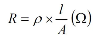
Here
R = resistance
l = conductor length
A = conductor area.
Depending on what units we express l and A in we get different units of ρ. A common way is by expressing l in m(eter) and A in mm2 , ρ then gets the unit Ω.mm2/m. If we instead choose l in m and A in m2, the unit for r will be Ω.mm2/m, which usually is transformed to Ωm. That unit often is used for non-metallic materials. If we know the value of ρ expressed in Ω.mm2/m, that value has to be multiplied by the factor 10-6 to give the value in Ωm. Thus, 10-6 x Ω.mm2/m = 1 Ωm.
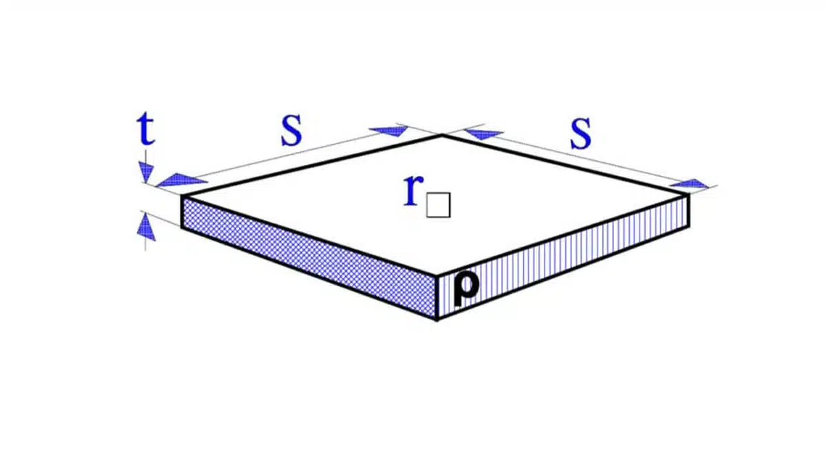
Sheet Resistivity (Ω/square)
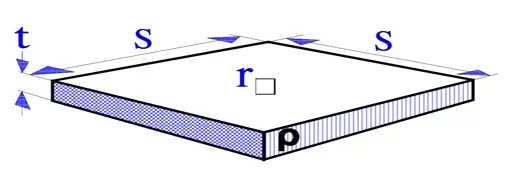
The sheet resistivity is a measure of the resistance per surface unit of resistive films. A square surface element as shown in Figure 1. gets according to the formula [1] the resistance:
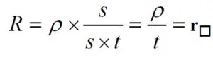
Thus, the resistance per square unit, r(sq), is independent of the surface size. It is the film thickness and its intrinsic resistivity that determine r(sq) (expressed in Ω/square).
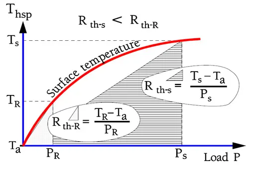
Surface Temperature and HOT SPOT
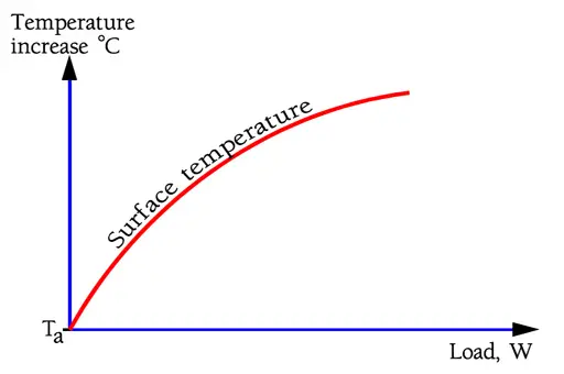
The surface temperature rise of the resistor body depends on the load as shown in principle in Figure R2. As temperature rises, conduction, radiation and convection (air-cooling) from the resistor body increases which causes the temperature curve to level off.
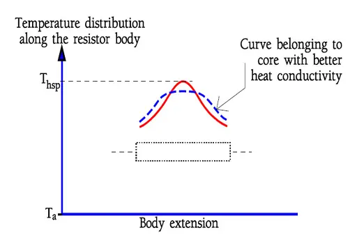
Figure 3. shows the temperature distribution along a resistor body. Thermal dissipation to the leads or SMD terminals decreases the temperature at the ends. In the middle of the body we register a temperature maximum, the so called Hot Spot temperature. This temperature determines both the resistor stability and life.
It is important that spiraling or wire winding be spread uniformly over the whole free resistor length. Otherwise we get an intensified Hot Spot effect that endangers life and stability.
It is not only for the resistor itself the Hot Spot is of vital importance. Heat radiation may have an effect on adjacent components and circuit boards. Thus, see that there is a satisfactory distance to the resistor body from heat-sensitive adjacent components.
Thermal Time Constant, τw
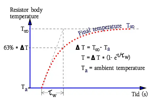
The thermal time constant, τw, is defined as the warm-up time for the resistor surface to attain 63% or theoretically (1-1/e) of the final temperature after applied load is increased in steps, usually PR (Figure 4). Of course, the time constant is strongly dependent on the resistor body size. It will be quicker to heat up a small body than a big one. Table 1 states standard values for some DIN classified sizes.
| DIN size | 0204 | 0207 | 0414 |
| Thermal time constant, τw (s) | 2 | 5 | 20 |
| Thermal resistance, Rth (K/W) | 400 | 250 | 170 |
Thermal Resistance, Rth
The thermal resistance, Rth, is expressed in K/W. It describes the temperature increase of a resistor body under applied load. Since radiation causes the temperature curve to turn downwards at increasing load data about Rth concerns normalized mounting and a load of PR. (See DIN 44 050). As shown in Figure 5. an power overload reduces the Rth.
In Equation [3] below the connection between Rth and current temperatures is described. Rth is expressed in K/W but due to the fact that the equation deals with the difference between two temperatures it doesn’t matter if we use °C or K for both values. The differences will be equally large. K2-K1 = [(°C2+273) – (°C1+273)] = °C2-°C1.
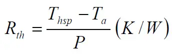
Thsp = Hot Spot temp. in K or °C
Ta = ambient temp. in K or °C.
P = applied load, W.
In Table 1. there are some examples of the thermal resistance for standard DIN sizes.
Temperature Coefficient of Resistance, TCR
The temperature coefficient of resistance, TCR, is expressed in ppm/°C.
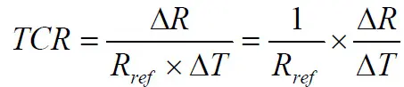
For clarification reasons TC is often written TCR, i.e., Temperature Coefficient of Resistance.
Specification limits and actual changes may look like the ones in following figure where a family of components are shown.
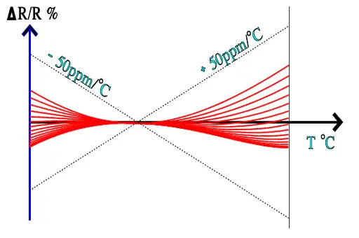
Temperature coefficient of resistance is of key importance especially at high precision resistors. In-depth article with more insights can be studied here:
Understanding High-Precision Resistor Temperature Coefficient of Resistance
Temperature Rise and Heating of Resistor
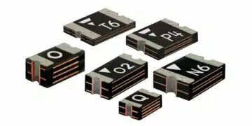
Resistor is an element that converts electric energy into heat energy. It always generates heat when the electric power is consumed and the temperature rises according to the consumed power. To control the temperature rise of a resistor, the generated heat needs to be dissipated efficiently. For chip resistors, the most of the generated heat conducted from the electrode to Cu foil pattern on the PCB, and finally dissipated to the air or chassis. As the image below, expanding the pad pattern of the resistor or expanding Cu foil pattern where the resistor is connected, will lead to good heat radiation and control the temperature rise.
Temperature rise of the resistor is also controlled by improving thermal conductivity of PCB; by thick Cu foil pattern, forming solid pattern on the back side of PCB or solid pattern inside the layer if it is a multilayer substrate. Wide terminal type flat chip resistors (reversed geometry) have excellent heat radiation characteristic and perform under high power. Examples of the wide terminal flat chip resistors are shown below. Forming the electrodes on long sides of this type of resistor, shortens the distance between the heat generating point and the electrode, enables to conduct much volumes of heat to PCB by large electrodes, which leads to improve heat radiation of resistor. The rated power is much more improved than that of standard resistor in same size.
Conclusion
Understanding resistivity, sheet resistivity, thermal resistance, thermal time constant, and TCR is essential for specifying resistors that remain stable and reliable under real operating conditions. Proper component selection combined with good PCB thermal design—larger copper areas, optimized pad layouts, and wide‑terminal chips—allows designers to control hot‑spot temperatures, minimize drift, and avoid thermally induced failures in both the resistor and surrounding circuitry.
FAQ about Resistor Resistivity and Thermal Resistance
Resistivity (ρ) is a material constant that describes how strongly a material opposes electric current, and it directly determines the resistance of a resistor together with its length and cross‑sectional area.
Sheet resistivity, expressed in Ω/square, is the resistance per square unit of a resistive film and depends only on the film thickness and intrinsic resistivity, not on the lateral dimensions of the square.
The hot spot is the maximum surface temperature point, typically in the middle of the resistor body, and it determines resistor stability, lifetime, and potential thermal impact on nearby components.
The hot spot is the maximum surface temperature point, typically in the middle of the resistor body, and it determines resistor stability, lifetime, and potential thermal impact on nearby components.
The thermal time constant (τw) is the time required for a resistor surface to reach about 63% of its final temperature after a step increase in load, and it depends strongly on the resistor body size.
The temperature coefficient of resistance (TCR), in ppm/°C, quantifies how a resistor’s resistance value changes with temperature and is especially critical for high‑precision resistors.
Expanding the resistor pad pattern, using larger copper areas, thicker copper, and solid inner or backside copper planes improves heat conduction to the PCB and reduces the resistor temperature rise.
Wide‑terminal (reversed geometry) chip resistors shorten the distance between the heat‑generating element and electrodes, improving heat conduction to the PCB and enabling a higher rated power in the same footprint.
How to Design Resistors for Optimal Thermal Performance and Stability
- Step 1 – Define the required resistance and power rating
Start by determining the nominal resistance value and the maximum continuous and peak power the resistor will dissipate in your application.
- Step 2 – Choose suitable resistive material and resistivity
Select a resistor technology and material with a resistivity that allows you to achieve the target resistance within practical dimensions and cost.
- Step 3 – Consider sheet resistivity for film resistors
For thin or thick film resistors, use sheet resistivity (Ω/square) to set film thickness and geometry so the resistance can be realized while maintaining good manufacturability and stability.
- Step 4 – Evaluate thermal resistance and hot spot temperature
Check the thermal resistance Rth of the chosen package and calculate the expected hot spot temperature rise at the rated and overload power levels to ensure adequate margin to the maximum permissible temperature.
- Step 5 – Account for thermal time constant in transient loads
Use the thermal time constant τw to understand how quickly the resistor heats under step loads, and verify that short pulses do not cause excessive surface temperature even if average power is within limits.
- Step 6 – Select an appropriate TCR range
Choose a resistor series with a TCR compatible with your accuracy requirements, especially for precision and sensing applications where temperature‑driven resistance drift must be minimized.
- Step 7 – Optimize PCB copper area and layout
Increase pad size and connected copper area, use thicker copper or solid planes, and respect clearance to heat‑sensitive components to improve heat spreading and reduce local temperatures.
- Step 8 – Use wide‑terminal chips for higher power density
Where high power in limited space is needed, select wide‑terminal chip resistors to enhance heat conduction into the PCB and improve power rating in the same footprint.
- Step 9 – Verify performance against datasheet limits
Compare calculated temperatures and resistance changes with the manufacturer’s derating curves, TCR limits, and lifetime specifications to confirm reliable operation over the full operating range.