Passive Components Blog
No Result
View All Result
  • Home
  • NewsFilter
    • All
    • Aerospace & Defence
    • Antenna
    • Applications
    • Automotive
    • Capacitors
    • Circuit Protection Devices
    • electro-mechanical news
    • Filters
    • Fuses
    • Inductors
    • Industrial
    • Integrated Passives
    • inter-connect news
    • Market & Supply Chain
    • Market Insights
    • Medical
    • Modelling and Simulation
    • New Materials & Supply
    • New Technologies
    • Non-linear Passives
    • Oscillators
    • Passive Sensors News
    • Resistors
    • RF & Microwave
    • Telecommunication
    • Weekly Digest

    TDK Extends SMT Gate Drive Transformers to 1000 V

    Non-Linear MLCC Class II Capacitor Measurements Challenges

    Researchers Demonstrated HfO Anti-Ferroelectric Flexible Capacitors

    Connector Industry Achieves Double-Digit Growth

    Stackpole Unveils Metal Element High Current Chip Jumpers

    Common Mistakes in Flyback Transformer Specs

    Vishay Releases Miniature SMD Trimmers for Harsh Environments

    Würth Elektronik Releases Push-Button and Main Switches

    Littelfuse Unveils High-Precision TMR Angle Magnetic Sensors

    Trending Tags

    • Ripple Current
    • RF
    • Leakage Current
    • Tantalum vs Ceramic
    • Snubber
    • Low ESR
    • Feedthrough
    • Derating
    • Dielectric Constant
    • New Products
    • Market Reports
  • VideoFilter
    • All
    • Antenna videos
    • Capacitor videos
    • Circuit Protection Video
    • Filter videos
    • Fuse videos
    • Inductor videos
    • Inter-Connect Video
    • Non-linear passives videos
    • Oscillator videos
    • Passive sensors videos
    • Resistor videos

    Non-Linear MLCC Class II Capacitor Measurements Challenges

    Percolation Phenomenon and Reliability of Molded Power Inductors in DC/DC converters

    Root Causes and Effects of DC Bias and AC in Ceramic Capacitors

    How to Calculate the Output Capacitor for a Switching Power Supply

    Switched Capacitor Converter Explained

    Understanding Inductor Dot Markings and Their Application in LTspice

    Accelerating Full Bridge LLC Resonant Converter Design with Frenetic AI

    Understanding Switched Capacitor Converters

    Coupled Inductors Circuit Model and Examples of its Applications

    Trending Tags

    • Capacitors explained
    • Inductors explained
    • Resistors explained
    • Filters explained
    • Application Video Guidelines
    • EMC
    • New Products
    • Ripple Current
    • Simulation
    • Tantalum vs Ceramic
  • Knowledge Blog
  • Suppliers
    • Who is Who
  • Events
No Result
View All Result
Passive Components Blog
No Result
View All Result

Ripple Current and MLCC: Basic principles; Kemet Tech Paper

7.5.2021
Reading Time: 6 mins read
A A

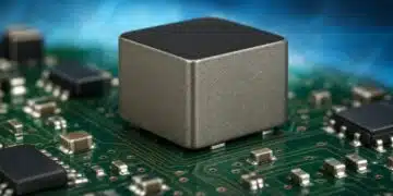
When talking about ripple current in capacitors, terms like ESR, overheating, lifetime and reliability cannot be out of the conversation. Choosing the correct solution by considering the ripple current of the application could prevent shorter component lifetime. See Kemet Technical paper that explains the basic principles.

WHAT IS RIPPLE CURRENT?

RelatedPosts

Tantalum Capacitor History

Understanding the Influence of ESR and Ripple Current for the Capacitor Selection

Resonant MLCC OBC Application Guide

Ripple current is the AC current that enters and leaves the capacitor during its operation in a circuit.
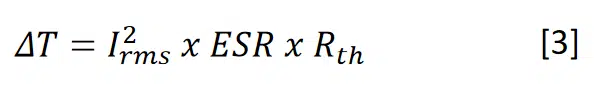
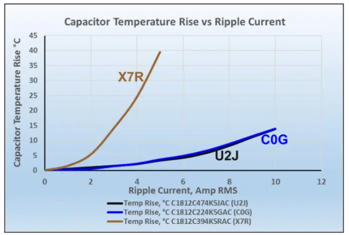
Ripple current generates heat and increase the temperature of the capacitor. This rate of heat generation in a capacitor can be described by using the common power formula:


Pdis = power dissipated
Irms = rms value of the ripple current
ESR = equivalent series resistance

HEAT AND RIPPLE CURRENT RELATION

As there is a heat generation, there is also a rate of heat removal (Prem) from the capacitor:

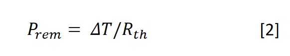
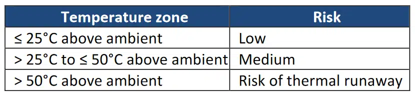
Rth is the thermal resistance (°C/watt)
ΔT is the temperature rise of the capacitor (°C)

At steady state Pdis = Prem, so:

It is important to mention that is influenced by factors as MLCC design, ambient temperature, PCB characteristics, circuit design, pads, trace thickness, etc.

Figure 1 –Temperature rise comparison by dielectrics.

AC VOLTAGE CONSIDERATIONS

MLCCs normally rated at DC voltages still can be used in AC applications, but there are some considerations since DC ≠ AC (e.g. 100 VDC ≠ 100 VAC):

  • Heating due to losses (Current limited region)
  • High AC voltages (Voltage limited region)
Figure 2–AC Voltage VS AC Current limited regions

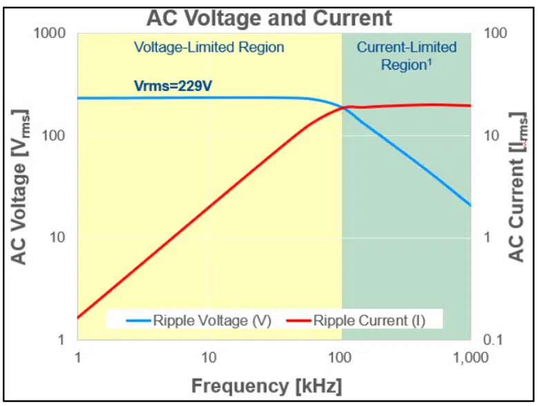
Heating due to I2R losses (Current limited region)

If the voltage is known, this equation can be used to calculate the AC current by following the conventional RLC equivalent circuit and capacitor parameters:

If AC Voltage is held constant, higher frequencies, as well as higher capacitance, result in higher AC currents, even with low AC voltages.

Power can be calculated by using equation [3] with capacitor and application parameters, in order to determine if the chosen MLCC is suitable for it.

Table 1–Thermal risk due to ripple current

High AC Voltages (Voltage limited region)

Figure 2 shows that at lower frequencies no more voltage is allowed, and the reason is that the amount of power dissipated is not high enough to overcome the following two rules for max voltage allowed for an MLCC.

Even if ripple current does not cause excessive heating, peak AC voltage (vp) needs to be considered.

Vp from AC waveform plus the DC voltage must be less than the rated DC voltage of the MLCC.

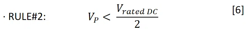
Vp from AC waveform must be less than the rated DC voltage of the MLCC divided by two.

Then, if the current is known, the AC voltage can be calculated by the following formula:

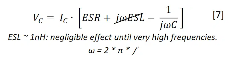
If AC Current is held constant, lower frequencies, as well as lower capacitance, results in higher AC voltages.

EXTERNAL FACTORS AFFECTING CURRENT

AC Current not only depends on the  losses, but also:

  • Ambient temperature.
  • Thermal characteristics of PCB.
  • Active/passive cooling of the MLCC.
  • Proximity of the part to other sources of heat.

FINAL RECOMMENDATIONS

When working with high ripple current, recommended MLCCs are Class I dielectrics which have a higher ripple current capability, compared against Class II. If more capability is needed, stacking capacitor solution as KEMET KC-LINK™ which is a Class I 150°C, could be an option.

This last technology is also available merged with KONNEKT™ Technology, that stacked in low loss orientation offers even a higher ripple current capability.

How to determine and measure MLCC ripple current and ESR

Related

Source: Kemet Electronics

Recent Posts

Non-Linear MLCC Class II Capacitor Measurements Challenges

19.8.2025
14

Researchers Demonstrated HfO Anti-Ferroelectric Flexible Capacitors

19.8.2025
7

Common Mistakes in Flyback Transformer Specs

15.8.2025
21

High Voltage MLCCs Meeting the Growing Demand for Efficiency in Power Conversion

12.8.2025
107

Radiation Tolerance of Tantalum and Ceramic Capacitors

8.8.2025
71

TDK Releases Compact Polypropylene Film Capacitors for Resonant Topologies

7.8.2025
33

Percolation Phenomenon and Reliability of Molded Power Inductors in DC/DC converters

6.8.2025
41

Root Causes and Effects of DC Bias and AC in Ceramic Capacitors

6.8.2025
56

Knowles Unveils High-Performance Safety-Certified MLCC Capacitors

6.8.2025
43

How to Calculate the Output Capacitor for a Switching Power Supply

6.8.2025
50

Upcoming Events

Aug 27
17:00 - 18:00 CEST

Capacitor Assemblies for High-Power Circuit Designs

Sep 3
15:30 - 17:30 CEST

How to Choose Your Magnetic Supplier

Sep 16
17:00 - 18:00 CEST

EMI Shielding Challenges

Sep 22
September 22 @ 13:00 - September 25 @ 15:15 EDT

Pre Cap Visual Inspection per Mil-Std-883 (TM 2017)

Sep 30
September 30 @ 12:00 - October 2 @ 14:00 EDT

MIL-Std-883 TM 2010

View Calendar

Popular Posts

  • Buck Converter Design and Calculation

    0 shares
    Share 0 Tweet 0
  • Boost Converter Design and Calculation

    0 shares
    Share 0 Tweet 0
  • Flyback Converter Design and Calculation

    0 shares
    Share 0 Tweet 0
  • LLC Resonant Converter Design and Calculation

    0 shares
    Share 0 Tweet 0
  • What is a Dielectric Constant and DF of Plastic Materials?

    4 shares
    Share 4 Tweet 0
  • Ripple Current and its Effects on the Performance of Capacitors

    3 shares
    Share 3 Tweet 0
  • Dual Active Bridge (DAB) Topology Explained

    0 shares
    Share 0 Tweet 0
  • How to Design an Inductor

    0 shares
    Share 0 Tweet 0
  • MLCC Case Sizes Standards Explained

    0 shares
    Share 0 Tweet 0
  • MLCC and Ceramic Capacitors

    0 shares
    Share 0 Tweet 0

Newsletter Subscription


Passive Components Blog

© EPCI - Leading Passive Components Educational and Information Site

  • Home
  • Privacy Policy
  • EPCI Membership & Advertisement
  • About

No Result
View All Result
  • Home
  • Knowledge Blog
  • Premium Suppliers

© EPCI - Leading Passive Components Educational and Information Site

This website uses cookies. By continuing to use this website you are giving consent to cookies being used. Visit our Privacy and Cookie Policy.
Go to mobile version