


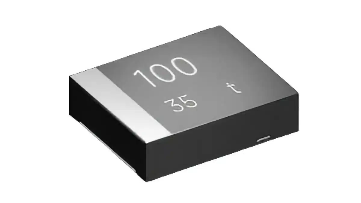
YMIN has introduced ultra‑low‑profile polymer tantalum capacitors in the 47–100 µF / 35 V range specifically targeted at power‑loss protection (PLP) circuits in new EDSFF and ultra‑thin U.2 SSDs.
These tantalum capacitor devices address the combination of aggressive height limits (1.5–1.9 mm), demanding PLP high energy density requirements and tight supply‑chain constraints in AI server platforms.
Introduction: PLP constraints in modern SSDs
With the transition from legacy 2.5″ U.2 and M.2 SSDs to EDSFF formats such as E1.S, E3.S, E1.L and E3.L, storage density per server unit has increased by a factor of roughly two to five, but available PCB volume for PLP components has shrunk dramatically. At the same time, AI workloads drive sustained high write activity and elevated ambient temperatures, so PLP circuits must reliably support millisecond‑class hold‑up time during unexpected power loss rather than just “best‑effort” protection. In this context, the choice of PLP capacitor now sets the practical upper limit of SSD performance and data integrity rather than being a secondary detail.
Key features and benefits
Space‑optimized for strict height limits
- Height grades of 1.9 mm (TQD19, TQW19) and 1.5 mm (TQD15) explicitly matched to:
- E1.S / E3.S single‑sided boards with 2.05 mm maximum component height
- Ultra‑thin 5 mm U.2 SATA boot SSDs with around 1.6 mm board‑side height budget
- 7.3 mm body length across the series to align with existing SSD power‑rail footprints and routing constraints.
High energy density at 35 V rating
- Capacitance range of 47 µF, 68 µF and 100 µF at 35 V allows PLP rails in the 12 V class to be buffered without derating the voltage rating into marginal territory.
- High‑density polymer tantalum core and thin packaging maintain both capacitance and voltage rating despite the reduced profile, avoiding the common compromise of shrinking capacitance to meet height.
Bottom‑terminal structure and low ESL
- Bottom‑terminal design shortens the current loop compared with conventional side‑terminal molded parts, cutting equivalent series inductance by approximately 50% according to YMIN internal comparison.
- Reduced ESL improves high‑frequency transient performance in PLP discharge and during normal operation, compensating in practice for slightly higher ESR than some reference parts.
Solid‑state reliability for 24/7 AI workloads
- All‑solid polymer tantalum construction eliminates liquid electrolyte dry‑out and supports fast, repetitive charge/discharge cycles typical in PLP.
- Operating temperature range from −55 °C to +105 °C covers typical AI server SSD environments with margin, including dense front‑pluggable NVMe shelves.
Localization and supply‑chain benefits
- Designed as drop‑in or near drop‑in replacements for thin Panasonic TQS series parts (for example 35TQS47MEU in 7343‑1.4 mm outline) with enhanced local supply.
- Target lead times of roughly 4–6 weeks, significantly shorter than typical 12‑week cycles for many imported polymer tantalum series, helping purchasing teams de‑risk ramps.
Typical applications
YMIN positions these polymer tantalum capacitors for PLP energy storage in SSDs, but the geometry and electrical characteristics also match other compact high‑reliability boards:
- PLP rails in E1.S and E3.S NVMe SSDs used in AI and cloud servers.
- PLP on ultra‑thin 5 mm U.2 SATA boot drives in 1U/2U servers.
- High‑density NVMe storage nodes where only single‑sided assembly is possible due to thermal or mechanical constraints.
- Other low‑profile storage or controller boards that need millisecond‑level hold‑up at 12 V with tight z‑axis budgets, subject to validation against the manufacturer datasheet.
In all of these cases the combination of 35 V rating, solid‑state polymer electrolyte and controlled ESL makes the series suitable for use as the main PLP energy storage element, sometimes supplemented by MLCCs for very high‑frequency decoupling.
Recommended PLP capacitor options
The table below summarizes the three key PLP options given in the manufacturer overview for AI server SSDs.
| Application scenario | Series / value | Voltage rating | Dimensions (L×W×H, mm) | Noted benefit |
|---|---|---|---|---|
| E1.S / E3.S SSD (2.05 mm height limit) | TQD19 68 µF | 35 V | 7.3 × 4.3 × 1.9 | Meets 1.9 mm height limit |
| E1.S / E3.S SSD (higher capacitance) | TQW19 100 µF | 35 V | 7.3 × 6.0 × 1.9 | Higher PLP energy at same height |
| U.2 5 mm ultra‑thin SATA boot SSD (1.6 mm limit) | TQD15 47 µF | 35 V | 7.3 × 4.3 × 1.5 | 1.5 mm profile for double‑sided layouts |
Exact capacitance tolerance, ripple current ratings and endurance should be taken from the respective series datasheets to avoid guessing any limits.
Technical highlights
Electrical characteristics relevant to PLP
From a PLP design perspective, three parameters dominate: capacitance at the operating voltage, ESR and ESL.
- Capacitance values of 47–100 µF at 35 V support hold‑up windows on the order of several milliseconds on a 12 V rail, depending on load current and number of devices in parallel; the manufacturer cites an example configuration achieving about 11.5 ms hold‑up with zero data loss in SSD testing.
- ESR for TQW19 is specified around 120 mΩ at the reference frequency, versus roughly 100 mΩ for a comparable Panasonic TQS device; in PLP use this modest increase is offset by the significantly reduced ESL and low overall loop resistance.
- The bottom‑terminal structure, combined with a wide‑body package where used, helps reduce both inductive and contact resistances, so the effective charge and discharge path is optimized for fast transient conditions.
For engineers, this means that simply comparing ESR figures at 100 kHz between different series may not reflect real PLP performance; the full loop impedance and board layout must be considered together with the capacitor structure.
Mechanical and environmental parameters
- Package outlines correspond to common 7.3 mm length molded chip footprints used in SSD power sections, facilitating reuse of reference designs that previously relied on thinner imports.
- Heights of 1.9 mm (TQD19, TQW19) and 1.5 mm (TQD15) are specifically selected against EDSFF and 5 mm U.2 stack‑up constraints, where even 0.1–0.2 mm overruns can cause interference with lids or thermal frames.
- All series are specified for operation from −55 °C to +105 °C, which is important for SSDs located close to hot CPUs or accelerators, especially in AI servers where continuous workload pushes case temperatures.
Where lifetime or derating curves versus temperature and ripple current are needed, designers should refer to the series‑specific datasheets, as the press release only provides headline environmental ratings.
Design‑in notes for engineers
Mapping PLP requirements to capacitor choice
- Start from the required PLP hold‑up time, operating voltage and maximum load current of the SSD controller and DRAM rather than from legacy capacitor values; AI workloads and larger DRAM caches often require higher energy than previous designs.
- Use 35 V rating with appropriate derating for 12 V PLP rails, then compute the approximate capacitance needed; YMIN’s 68 µF and 100 µF options at 1.9 mm height allow designers to stay within mechanical limits while meeting energy targets.
- For ultra‑thin 5 mm U.2 boot SSDs, treat 1.5 mm capacitor height as a hard constraint and evaluate whether a single 47 µF / 35 V device (TQD15) or several in parallel are needed to meet the PLP budget.
Layout and loop‑impedance considerations
- Take advantage of the bottom‑terminal structure by minimizing loop area between the capacitor terminals, MOSFETs and controller supply pins; this reduces effective ESL beyond the component‑level improvement.
- Place small MLCCs close to controller pins if additional high‑frequency decoupling is required, using the polymer tantalum as the main energy reservoir for millisecond‑scale events.
- Pay attention to thermal coupling between the capacitor and hot components; although rated up to 105 °C, continuous operation near the upper limit will reduce lifetime compared with cooler installation.
Validation and qualification
- Perform board‑level PLP testing using worst‑case system profiles, including high‑temperature, maximum write‑activity and abrupt power‑cut scenarios, to validate that hold‑up time and data‑integrity targets are achieved.
- Compare not just ESR but measured charge time and discharge behavior between existing Panasonic TQS‑based designs and YMIN’s TQD/TQW/TQD15 solutions, to capture the benefit of reduced ESL and total loop resistance.
- Coordinate with purchasing to leverage the shorter lead‑time and localization benefits while ensuring second‑source or fallback strategies are in place where qualification procedures require them.
Source
This article is based on information provided in an official YMIN press release and associated product pages, complemented by general engineering interpretation of PLP design considerations. Exact numerical limits and curves should always be confirmed against the latest manufacturer datasheets.


