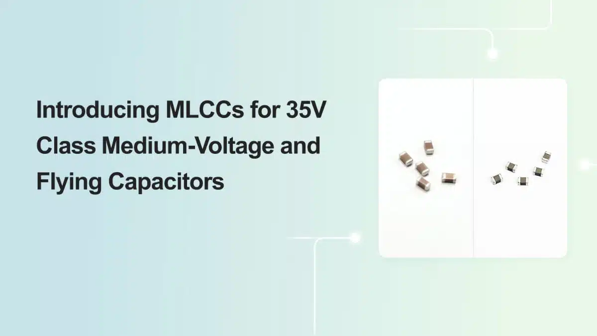
Samsung Electro-Mechanics has introduced a set of MLCC ceramic capacitors aimed at 35 V class medium-voltage nodes and flying capacitor roles in high-efficiency charge pump circuits for super-fast smartphone charging.
These MLCC ceramic capacitors target designers who are shifting from 25 V to 35 V rated MLCCs in USB PD 3.0/3.1 environments and need low ESR, high-capacitance parts that fit tight mobile form factors.
Why 35 V MLCCs matter in fast charging
As smartphone chargers move into the 60 W and 100 W-plus class, USB Power Delivery 3.0/3.1 profiles typically use cable voltages around 20 V to avoid excessive I²R losses and heat in the cable and connectors. In practice, design guidelines recommend operating MLCCs at only about half to sixty percent of their rated voltage to provide margin against surges and transient events in the power path. This pushes the required MLCC voltage rating for 20 V rails from traditional 25 V devices up to 35 V class parts in order to maintain reliability over life and under worst-case conditions.
In parallel, battery charging systems inside smartphones increasingly use high-voltage, low-current topologies or switched-capacitor charge pumps instead of purely low-voltage, high-current schemes. In such architectures, 35 V rated MLCCs on the input and intermediate nodes are expected to become the standard even for mid-range devices, not only for flagship phones.
Flying capacitors in charge pump fast chargers
In many current designs, the external charger raises the cable voltage to a range typically between 10 V and 20 V to deliver high power while keeping current and connector heating under control. Inside the phone, a charge pump stage then converts the higher input voltage down to a lower battery charge voltage (around 5 V typical) by dividing the voltage ratio and increasing current accordingly. The flying capacitor is the key energy transfer element in this switched-capacitor converter, alternately connected between different nodes to move charge while minimizing switching and redistribution losses.
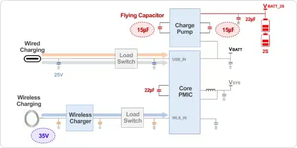
Unlike a conventional MLCC that often has one terminal referenced to ground, a flying capacitor toggles both terminals between different potential levels as the charge pump phases alternate. This “floating” behavior is the origin of the term flying capacitor and imposes specific requirements on capacitance stability, ESR, and reliability under high dv/dt and switching stress. The use of MLCCs with low ESR directly improves the efficiency of the charge pump stage, helping designers reach overall converter efficiencies in the high ninety percent range while keeping device temperatures under control during 60 W and above charging.
Key features and benefits
For the fast charging ecosystem around smartphones and other mobile devices, Samsung Electro-Mechanics highlights several important characteristics of its 35 V class and flying capacitor MLCCs:
- Medium-voltage rating aimed at systems using approximately 20 V USB PD rails with appropriate voltage derating in line with common design practices.
- High capacitance in small case sizes, allowing designers to replace larger or multiple components while preserving or improving transient performance.
- X5R dielectric, supporting a typical operating temperature range from −55 °C to +85 °C with reasonably stable capacitance in common mobile environments.
- Low ESR characteristics, which help minimize charge pump conduction and switching losses and reduce ripple and self-heating.
- Thin profiles (down to around 0.8 mm maximum thickness depending on part number), which are well suited for the tight z‑height constraints inside smartphones and similar portable electronics.
- Use of MLCCs instead of inductors in the charge pump power stage, reducing height and weight and simplifying EMI behavior compared with inductor-based DC‑DC converters.
From a system perspective, the combination of higher voltage rating, adequate derating margin, and low ESR helps maintain both efficiency and long-term reliability in compact, high-power charging hardware.
Technical highlights
Product lineup overview
The announced MLCC lineup in this context includes two 0603 (1608 metric) 35 V parts positioned for 20 V class medium-voltage rails, and one 0402 (1005 metric) device intended as a flying capacitor in charge pump stages.
| Part number | Size (inch/mm) | Capacitance | Rated voltage | TCC | Max thickness | Remarks |
|---|---|---|---|---|---|---|
| CL10A106ML6NRN# | 0603 / 1608 | 10 µF | 35 V DC | X5R | 0.8 mm | – |
| CL10A106ML86RN# | 0603 / 1608 | 10 µF | 35 V DC | X5R | 1.0 mm | Metal Epoxy |
| CL05A156MPENZN# | 0402 / 1005 | 15 µF | 10 V DC | X5R | 0.8 mm | Flying Capacitor |
The 0603 35 V devices address the trend toward higher bus voltages in USB PD based fast chargers, while the 0402 10 V part is tuned for the internal flying capacitor nodes, which typically see lower absolute voltage but high dynamic stress and demanding ESR and capacitance requirements in a very small footprint.
Electrical and thermal behavior
X5R MLCCs are widely used in power paths because they combine relatively high volumetric capacitance with acceptable stability over typical consumer operating temperatures. Designers should nevertheless account for voltage and temperature-dependent capacitance variation when dimensioning charge pump stages, especially for the 0402 device used as the main flying capacitor element. The low ESR emphasized for these parts reduces ripple on the flying node, helps keep converter efficiency in the high nineties, and directly lowers self-heating of the MLCC and surrounding components.
Mechanical aspects such as the metal epoxy construction of CL10A106ML86RN# can also be relevant in thin smartphone boards with complex assembly processes, where solder joint reliability, board flex, and drop performance impose additional constraints. Here, careful layout and pad design, along with controlled assembly parameters, help exploit the full benefits of the higher voltage rating and high capacitance without compromising mechanical robustness.
Typical applications
These MLCCs are aimed primarily at high-power mobile device charging and power management but can also be considered in other compact electronics requiring efficient switched-capacitor stages.
Typical usage scenarios include:
- USB PD 3.0/3.1 based smartphone chargers and charging ports with 60 W or higher power ratings.
- Input and intermediate node decoupling in power management ICs that operate at approximately 20 V rails derived from USB PD.
- Internal smartphone charge pump stages that convert elevated input voltages down to battery charging levels using flying capacitor architectures.
- Compact power stages in tablets, handheld gaming consoles, power banks, and similar devices that adopt high-voltage, low-current charging profiles.
- Other high-density portable equipment where inductors are undesirable due to height, cost, or EMI concerns, and where high-efficiency switched-capacitor converters are implemented.
In charge pump topologies, CL05A156MPENZN# can be used as the primary flying capacitor in 2:1 or 4:1 conversion stages, while the 35 V 0603 parts serve as input, output, or intermediate node decoupling and energy storage elements on the higher-voltage side.
Design-in notes for engineers
When designing fast charging paths based on USB PD 3.0/3.1 with 20 V rail operation, it is good practice to select MLCCs with rated voltage significantly above the maximum steady-state operating voltage. For most consumer electronics, operating MLCCs at roughly half of their rated voltage provides margin for transients and helps maintain capacitance over life, which justifies the shift from 25 V to 35 V parts on 20 V lines. The CL10A106ML6NRN# and CL10A106ML86RN# parts are aligned with this design philosophy for medium-voltage rails.
In flying capacitor roles, such as where CL05A156MPENZN# is intended, low ESR and sufficient capacitance at the actual DC bias are critical for charge pump performance. Engineers should perform worst-case analysis using the DC bias curves from the datasheet, taking into account the effective capacitance at the expected operating voltage rather than relying solely on nominal capacitance values. Layout should minimize loop inductance around the charge pump switches and the flying capacitor to reduce overshoot and ringing, while paying attention to thermal considerations in dense smartphone PCB areas.
From a supply chain perspective, using MLCCs that are already positioned for mass production in smartphone fast charging applications can reduce risk of obsolescence and improve availability. Aligning designs with standard case sizes like 0603 and 0402 in these specific voltage and capacitance ranges also eases second-sourcing efforts, even when some parameters such as ESR or mechanical construction differ between manufacturers.
Source
This article is based on information published by Samsung Electro-Mechanics in their product news about 35 V class medium-voltage and flying capacitor MLCCs and associated product lineup, complemented with general engineering context for fast charging and charge pump applications. For exact electrical characteristics and qualification data, always refer to the official manufacturer datasheets.