


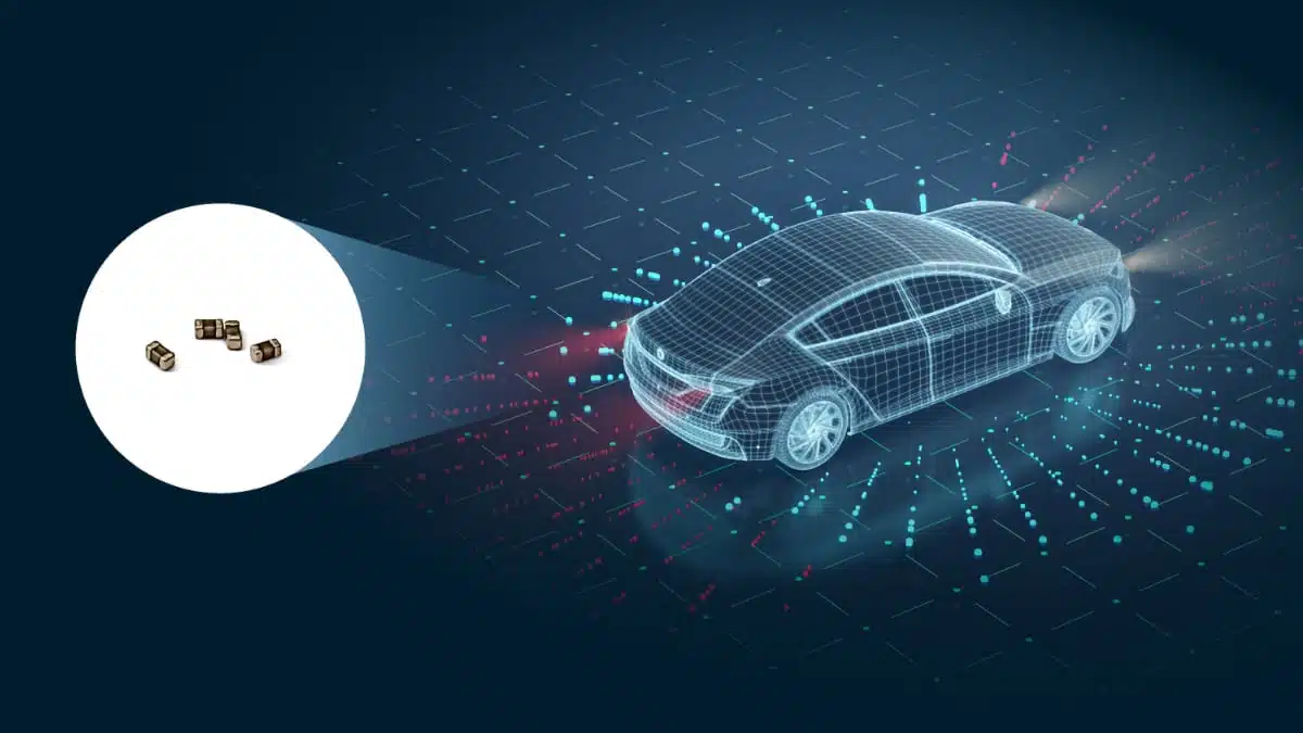
Samsung Electro-Mechanics has introduced an automotive-grade multilayer ceramic capacitor (MLCC) that combines 47 µF capacitance, 4 V rating and 0805 (2012 metric) size – claimed as the first of its kind for automotive use.
This Samsung Electro-Mechanics ultra-high-capacitance MLCC device targets compact, high-current power rails in ADAS and in-vehicle infotainment (IVI) where board area, thermal performance and reliability are under pressure.
Key features and benefits
Samsung’s new device family is built around a flagship 47 µF part in an 0805 (2.0 × 1.25 mm) package for automotive applications.
- Ultra-high capacitance:
- 47 µF nominal capacitance in 0805 size for the lead product CL21Z476MRY6PN.
- 22 µF options (CL21Z226MQYVPN, CL21Z226MRYVPN) extend the series where lower capacitance or higher voltage is required.
- Voltage ratings:
- 4 V rated voltage for the 47 µF CL21Z476MRY6PN.
- 4 V and 6.3 V rated voltages for the 22 µF series parts, supporting a range of low-voltage rails in modern SoCs and sensors.
- Temperature characteristic:
- X7T dielectric with an operating temperature range from −55 °C to +125 °C.
- The parts are specified to be usable up to 125 °C without derating, which simplifies derating calculations in many ECUs where ambient and self-heating are well controlled.
- Package and footprint:
- Standard 0805 (2012 metric, 2.0 × 1.25 mm) footprint for straightforward routing and compatibility with existing designs.
- Small case size supports high-density layouts in space-constrained ADAS and IVI modules.
- Automotive qualification:
- Designed to meet AEC-Q200 requirements for automotive passive components, addressing vibration, thermal cycling and endurance criteria typical for ECUs.
For design teams, the ability to realize 47 µF in a single 0805 MLCC can reduce capacitor count, free PCB area and simplify placement compared with parallel banks of lower-capacitance MLCCs.
Typical applications
The MLCC family is positioned as a decoupling solution for modern automotive electronics where processing performance and integration are rapidly increasing.
- ADAS (Advanced Driver Assistance Systems):
- Power decoupling on high-performance application processors used for sensor fusion, object recognition and driver monitoring.
- Local bulk capacitance on low-voltage rails feeding cameras, radar modules and LiDAR controllers.
- IVI (In-Vehicle Infotainment):
- Decoupling for SoCs, memory and high-speed interfaces within head units and cockpit domain controllers.
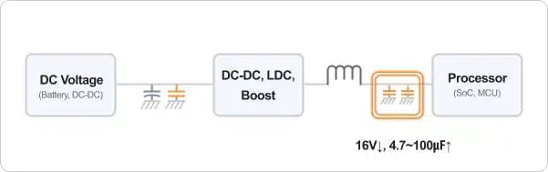
- Stabilization of DC/DC converter outputs supplying audio, connectivity and display subsystems.
- General automotive ECUs:
- Any module requiring compact bulk capacitance on low-voltage digital rails where ambient temperatures can reach up to 125 °C.
- Point-of-load (POL) converters close to high-current ICs where small case size and low ESR are beneficial.
In these applications, a single 47 µF 0805 device can often replace multiple smaller capacitors, reducing BOM complexity and improving layout flexibility in dense multilayer PCBs.
Technical highlights
Samsung attributes the performance of the new MLCC to proprietary ceramic and electrode material technologies combined with ultra-precision stacking processes.
- Dielectric system:
- X7T temperature characteristic supports −55 °C to +125 °C operation with defined capacitance change over temperature.
- X7T is particularly suitable for compact bulk decoupling in environments where Class II behavior is acceptable but elevated temperature stability is still needed.
- High reliability and low ESR:
- The product is presented as offering high reliability suitable for automotive use, supported by AEC-Q200 compliance.
- Low ESR (equivalent series resistance) helps reduce supply ripple and improve transient response in high di/dt circuits common in ADAS and IVI power rails.
- Space saving and design flexibility:
- Achieving 47 µF in 0805 format enables designers to reduce the number of MLCCs in parallel or shrink the occupied footprint when compared to using multiple lower-capacitance capacitors.
- The availability of 22 µF variants at 4 V and 6.3 V gives flexibility to align capacitance, voltage margin and footprint across different rails within the same ECU platform.
As always with high-capacitance Class II MLCCs, engineers should take into account capacitance variation with DC bias, temperature and AC load according to the manufacturer datasheet when designing margins.
Design-in notes for engineers
When designing in these MLCCs, a few practical considerations can help ensure robust performance in automotive systems.
- Voltage derating and bias:
- Even though the new 47 µF part is rated at 4 V and stated to be usable up to 125 °C without derating, typical automotive practice is still to allow some margin between operating voltage and rated voltage.
- For low-voltage digital rails (for example 1.0–1.8 V), this device provides ample headroom while keeping DC bias-induced capacitance loss manageable according to the datasheet characteristics.
- Placement and layout:
- For decoupling, place the capacitor as close as possible to the IC power pins or DC/DC converter outputs to minimize loop inductance.
- Consider using multiple vias to connect to power and ground planes to exploit the low ESR and minimize ESL benefits of the MLCC.
- Thermal environment:
- The X7T characteristic up to 125 °C makes the parts suitable near heat sources such as processors and power stages, but ambient and self-heating should still be evaluated to remain within specified temperature limits.
- In tightly packed ADAS and IVI ECUs, thermal simulation or measurement can help confirm that capacitor body temperature stays within the intended operating range.
- Reliability and qualification:
- As AEC-Q200 compliant devices, these MLCCs are suitable for automotive grade applications subject to OEM-specific validation.
- For safety-related functions, system-level FMEA should still consider capacitor failure modes, including open and short scenarios, and appropriate redundancy or protection.
- Sizing and alternatives:
- Designers migrating from electrolytic or tantalum capacitors in low-voltage sections may benefit from lower ESR and smaller size but should verify start-up behavior and control loop stability of regulators when switching to high-capacitance MLCCs.
- The 22 µF, 6.3 V option is a candidate for rails where higher voltage margin is required, for example 3.3 V lines or boosted supply nodes inside camera or radar modules.
Early engagement with the full datasheet and, where possible, evaluation samples is recommended to fine-tune the number of capacitors, their placement and derating strategy in each specific ECU design.
Source
This article is based on information provided by Samsung Electro-Mechanics in their official product news communication for the automotive ultra-high-capacitance X7T 0805 MLCC series, complemented by general industry design practices for automotive MLCC application.