


This blog article written by Johnson Jiang, KYOCERA-AVX Components Corporation, elaborates on how SuperCapacitors work, their construction, essential applications, SuperCapacitors benefits in power back up applications, and key advantages over other energy storage solutions.
Introduction
Electric double-layer capacitors (EDLCs) are electrochemical capacitors called “SuperCapacitors,” or supercaps, due to their high energy density.
Compared to traditional electrolytic capacitors, SuperCapacitors store electrical energy about two to three orders of magnitude higher and achieve several hundred thousand to millions of charge/discharge cycles. This advantage comes from the special construction of SuperCapacitors.
Advances in SuperCapacitor technology have made these products viable energy storage solutions over conventional battery systems for providing reliable backup power in a host of applications.
Supercapacitor Construction and Modes of Operation
In traditional capacitors, charges move under the force of the electric field. Placing a medium between the conductors (dielectric) hinders the movement of charges, causing an accumulation on the conductor and storage of charges.
The amount of stored charges is what is referred to as capacitance. Think of electrolytic SuperCapacitors as two non-reactive porous electrode plates suspended in an electrolyte. When the plates are electrified, the ions with opposite polarity in the electrolyte form two close charge layers on both sides, which is similar to the capacitance effect of the plate capacitor to achieve the purpose of energy storage.
Because the energy storage capacity of a capacitor is proportional to the plane area of the electrode, porous activated carbon materials or copper sulfides are often used on the electrode surface, and the effective area is up to 100,000 times greater than that of a smooth surface. Consequently, SuperCapacitors’ storage capacity (electrostatic capacity) is exponentially larger than that of standard capacitors.
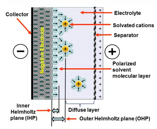
Unlike traditional capacitors, SuperCapacitors do not utilize dielectrics. The EDLC construction comprises two electrodes immersed in an electrolyte with a separator that is ionically connected via the electrolyte. When a voltage is applied, both electrodes in the SuperCapacitor generate two electrical layers of charges of opposing polarity; one in the lattice structure of the electrodes and another in the electrolyte.
The electric double layers become separated via a boundary known as the Helmholtz plane. This layer allows positive and negative ions within the electrolyte to pass from one side to another. The electrolyte itself does not conduct electrons, so there will be no leakage inside the capacitor after charging. During discharge, electrons on the electrode flow from one pole to the other through an external circuit, resulting in a significant reduction in the adsorption of ions between the electrode and the electrolyte, and the positive and negative ions within the electrolyte are redistributed evenly. This special construction ensures that SuperCapacitors are more beneficial in many aspects of reliability and performance compared to traditional capacitors and other energy storage technologies.
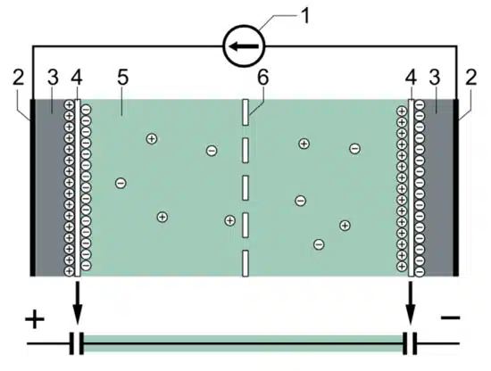
Compared to standard capacitors, EDLCs offer power densities up to 1000 times higher than standard capacitors. However, unlike capacitors, an EDLC discharges much slower – comparable to a battery. Figure 2 illustrates the typical construction of an EDLC.
Addressing Power Quality Issues with Supercapacitors
Voltage sags are the most costly of all power quality issues in commercial and industrial plants due to numerous issues, including distribution line failures, load spikes in utility service areas, or discrete load increases, e.g., additional motor starting. The deviation of power quality events can reach between 10% to 90% of the rated voltage.
With increased renewable energy infrastructure connected to the public grid, there will be more deviation and more transient voltage sags. Without appropriate measures to stabilize power quality, commercial and industrial facilities face high risks of lower production volumes, manufacturing waste, reduced labor efficiency, and costly damage to sensitive manufacturing equipment.
Industrial equipment with sensitive loads, including programmable logic controllers (PLCs), adjustable speed drives, laser manufacturing equipment, robotic systems, industrial computers, and information technology (IT) equipment, are more vulnerable to voltage interruptions outside the ANSI c.84.1, CBEMA, ITIC, and SEMI-10 power quality specifications. Dynamic voltage restorers (DVRs) are useful for addressing interruptions that negatively impact power supply quality. Similarly, energy storage is essential for stabilizing output during voltage drops and the introduction of large loads.
SuperCapacitors can provide DVR or backup power to keep critical systems operational for short periods (several minutes after a power outage). These products are scalable and can ensure adequate coverage by injecting power to support facilities, microgrids, and utilities while reducing the risk of costly downtime.
Today, SuperCapacitors are being integrated into a wide range of devices and equipment. They can serve as main energy storage or combine with existing systems to increase the lifespan, optimize runtime, and lower costs. In numerous manufacturing processes, reliable backup power is critical, as brownouts or total loss of power for even a few seconds could result in equipment failures and costly downtime. Equipment shutdowns, for instance, can result in economic losses of tens to hundreds of thousands of dollars, which can add up to millions of dollars annually.
SuperCapacitor modules comprising units of individual cells can provide high-density backup or ride-through power in industrial settings for a short period until the primary power supply is restored. Consumers from all walks of life, especially manufacturing plants, information services, finance, and telecommunications businesses, need high-quality and reliable power to operate electronic equipment.
Utility companies, PUC, independent standards bodies, and NERC specify stringent voltage and frequency control requirements to ensure output power integrity and reliability. Advanced energy storage systems comprising SuperCapacitors can provide ultra-fast response times to ensure real-time power quality in the event of power quality events.
Advantages of Using Supercapacitors
SuperCapacitors offer several benefits over alternative energy storage solutions, including faster response times, lower capital expenditure (CAPEX), longer service life, small footprints, etc.
Faster Response Times:
Since they charge to full capacity very quickly (ranging from seconds to minutes), SuperCapacitor modules can transfer stored energy at full power almost instantaneously, unlike batteries or flywheels. Thus, they are more efficient at responding to outages or sag events.
Lower Capital Expenditure:
SuperCapacitor-based energy storage can be up to 2-3 times cheaper than batteries for addressing voltage drop issues as batteries need to be of larger sizes to meet power and service life requirements in most applications.
Memory Consumption:
A SuperCapacitor’s high energy storage capacity makes the memory consumption of a storage system significantly lower than that of a battery UPS system.
Long Service Life and Low Operating Costs:
SuperCapacitor technology provides 12 to 15years without maintenance or replacement. They are electrostatic devices designed to charge and discharge repeatedly over a full cycle or microcycle. Supercaps have been proven to achieve over one million reference charge-discharge cycles. Moreover, as there are no moving parts, they do not require annual maintenance.
Temperature Stability:
SuperCapacitors offer high stability in a host of operating temperatures. Unlike batteries, there is no risk of a thermal runaway due to higher temperatures.
Hybrid Systems:
SuperCapacitor systems can be deployed alongside batteries to provide peak shaving for energy optimization in hybrid systems. They can act as a buffer to extend a battery’s service life, thus reducing the frequency of replacements and lowering operating costs. They are also widely used in real-time clock (RTC) backup applications to provide RTC circuits when power is disconnected.
Supercapacitor Pack Types
EDLCs function based on forming a double-layer capacitance at the electrode-electrolyte interface when a voltage is applied. These SuperCapacitors offer several benefits over alternative energy storage solutions, e.g., long lifetimes, small footprints, lower CAPEX, zero maintenance costs, and wide operating temperatures with no thermal runaway.
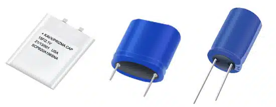
Prismatic Cell
PrizmaCapTM SuperCapacitors are based upon a propylene carbonate based electrolyte. A unique electrochemical combination allows the SuperCapacitor to operate across a wide temperature range (-55°C to +90°C). Current technology dictates capacitance range limitations between 1 and 500 farads with 3.5, 8.5 and 15 Farads being widely available capacitor values. These devices have a rated voltage of 2.1 V, when operating at <= +65°C and must be de-rated to 1.1 V when operating at +66°C to +90°C.
PrizmaCapTM capacitors offer many electrical advantages when compared to similar capacitance radial can SuperCapacitors. ESR (Equivalent Series Resistance) values are uniformly lower and are as low as 30 mΩ. The devices have approximately twice the capacitance density and 50% energy density improvements over traditional SuperCapacitors. PrizmaCapTM packages differ greatly from standard radial can SuperCapacitors. PrizmaCapsTM occupy a board area of 48mm x 45mm and have ultra low heigh board profiles of 0.8, 1.3 or 2mm. All PrizmaCapsTM are RoHS/REACH compliant and weigh < 2 grams.
Radial Can
Radial can AcN electrolyte SuperCapacitors offer designers maximum flexibility through:
- Multiple product series options available
- Multiple voltage offering
- Ten different case sizes
- Highest number of capacitance values available
Radial can parts are commonly used in single configuration for lower voltage designs or multiple cans configured to obtain the correct voltage/energy for higher voltage loads. Multiple cans can be balanced via active or passive methods. SuperCapacitor balancing is needed to ensure long life for multiple SuperCapacitors used in series. Balancing each SuperCapacitor prevents damage to other SuperCapacitors in the stack through over-voltage.
Passive balancing has the advantage of being the cheapest, smallest and easiest to use since its accomplished with a resistor. However, the big disadvantage is that passive balancing reduces efficiency since power is dissipated in the balancing resistor. Active semiconductor balancing is most efficient and exacting, but its costs are more significant. The size required for active balance solutions varies greatly based upon the number of cells in need of balancing as well as the size of cell/semiconductor types used in balancing.


