Passive Components Blog
No Result
View All Result
  • Home
  • NewsFilter
    • All
    • Aerospace & Defence
    • Antenna
    • Applications
    • Automotive
    • Capacitors
    • Circuit Protection Devices
    • electro-mechanical news
    • Filters
    • Fuses
    • Inductors
    • Industrial
    • Integrated Passives
    • inter-connect news
    • Market & Supply Chain
    • Market Insights
    • Medical
    • Modelling and Simulation
    • New Materials & Supply
    • New Technologies
    • Non-linear Passives
    • Oscillators
    • Passive Sensors News
    • Resistors
    • RF & Microwave
    • Telecommunication
    • Weekly Digest

    Designing a Custom Core Transformer for 10 kW LLC Data Center Power Stages

    Magnetics Design in High‑Frequency GaN Converters

    ECIA Industry Pulse April 2026: Sentiment Cools but Stays Strong

    Industrial Passive Components Markets and Technologies 2026

    Automotive Passive Components Technology Dossier

    Samsung Electro-Mechanics Signs 1.5T KRW Silicon Capacitor AI Contract

    Murata Expands Thermistor Production Capacity at Yokaichi Plant

    Hirose Expands Compact High‑Voltage EV connectors

    Qi2 Wireless Charging: Inductors, Capacitors and EMC Filters

    Trending Tags

    • Ripple Current
    • RF
    • Leakage Current
    • Tantalum vs Ceramic
    • Snubber
    • Low ESR
    • Feedthrough
    • Derating
    • Dielectric Constant
    • New Products
    • Market Reports
  • VideoFilter
    • All
    • Antenna videos
    • Capacitor videos
    • Circuit Protection Video
    • Filter videos
    • Fuse videos
    • Inductor videos
    • Inter-Connect Video
    • Non-linear passives videos
    • Oscillator videos
    • Passive sensors videos
    • Resistor videos

    Magnetics Design in High‑Frequency GaN Converters

    Qi2 Wireless Charging: Inductors, Capacitors and EMC Filters

    Two‑capacitor paradox explained for engineers

    Capacitances of Nonlinear MLCCs: What Datasheets Don’t Tell You

    Tapped Inductor Buck Converter Fundamentals

    Planar vs Conventional Transformer: When it Make Sense

    Modeling Fringing Field Losses in Inductors & Transformers

    Why Power Inductors Use a Ferrite Core With an Air Gap

    Transformer-Based Power-Line Harvester Magnetic Design

    Trending Tags

    • Capacitors explained
    • Inductors explained
    • Resistors explained
    • Filters explained
    • Application Video Guidelines
    • EMC
    • New Products
    • Ripple Current
    • Simulation
    • Tantalum vs Ceramic
  • Knowledge Blog
  • DossiersNew
  • Suppliers
    • Who is Who
  • PCNS
    • PCNS 2025
    • PCNS 2023
    • PCNS 2021
    • PCNS 2019
    • PCNS 2017
  • Events
No Result
View All Result
Passive Components Blog
No Result
View All Result

The THR Manufacturing Process

12.9.2021
Reading Time: 2 mins read
A A

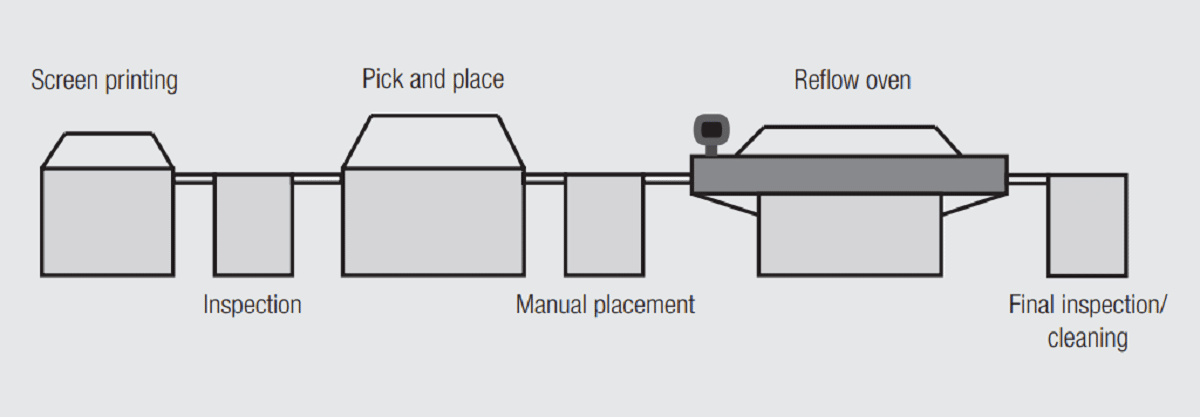
The basic requirement of a THR manufacturing process is to ensure compatibility with the existing SMT manufacturing process, typical stages of which are illustrated in Figure 2.86.

Fig. 2.86: Stages of a typical SMT/THR manufacturing line

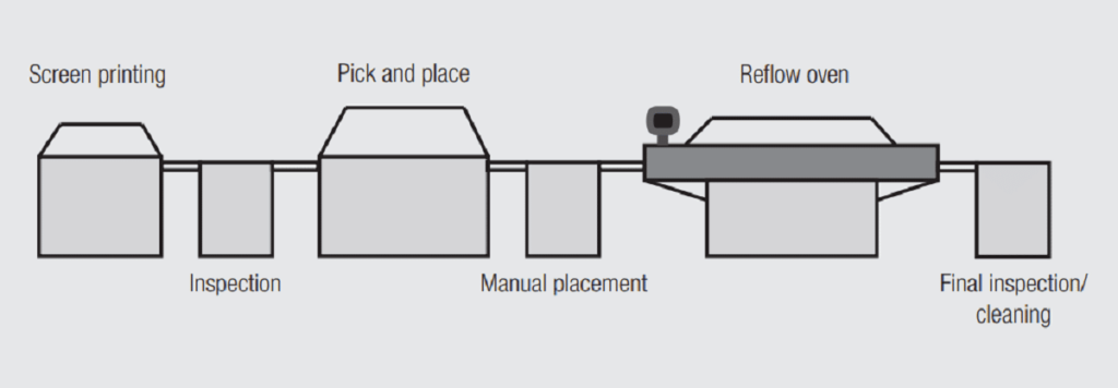
Stage 1: Screen printing: the solder paste is applied to the PCB.
Stage 2: Inspection: ensures the dimensional control and alignment of the screen printing process with the PCB.
Stage 3: Pick and place: puts the SMT, and any connectors which may also be pick and place compatible, onto the screened solder paste.
Stage 4: Manual placement: connectors are manually inserted into the PTH of the PCB.
Stage 5: Reflow oven: reflow soldering of the components onto/into the PCB via reflow soldering processes, typically vapor phase or convection reflow.
Stage 6: Final inspection: inspection using appropriate methods to ensure the proper placement of components and satisfactory soldered joints.
Stage 7: Cleaning: removes possible flux residues.

RelatedPosts

Polymer Materials and Processing

What is RF Connector

Connector Materials and Processes

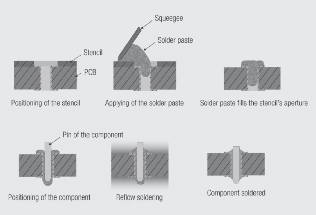
Figure 2.87 shows the status of the PCB with respect to the solder paste and soldering process through the manufacturing line. The first three illustrations show processes occurring in the screen printing stage as the solder paste is applied to the PCB, the fourth illustration shows the PTH after the connector insertion with the solder paste distribution in the PTH, the last two illustrations show the reflow process and the configuration of the soldered component.

Fig. 2.87: Stages of printing and soldering THR processes

Related

Source: Wurth elektronik

Recent Posts

Circular Connectors Coding

26.11.2025
117

Connector PCB Design Challenges

3.10.2025
84

Non-Magnetic Interconnects

23.4.2025
41

10 Tips for Ensuring Reliability of Discrete Wire Assemblies

20.2.2025
79

Polymer Materials and Processing

11.8.2025
180

Basic PCB Technology Overview

1.7.2025
37

What is RF Connector

17.12.2024
35

Creepage and Clearance of Connector

25.7.2025
67

RF Connector Types: How To Choose the Right One

24.4.2026
52

Upcoming Events

Jun 2
16:00 - 17:00 CEST

Calculation, Simulation and Measurement of 800V EMC Filters

Jun 16
16:00 - 17:00 CEST

EMC with EMC – EMC‑compliant design with electromechanical connectors

View Calendar

Popular Posts

  • Buck Converter Design and Calculation

    0 shares
    Share 0 Tweet 0
  • Boost Converter Design and Calculation

    0 shares
    Share 0 Tweet 0
  • Flyback Converter Design and Calculation

    0 shares
    Share 0 Tweet 0
  • LLC Resonant Converter Design and Calculation

    0 shares
    Share 0 Tweet 0
  • MLCC and Ceramic Capacitors

    0 shares
    Share 0 Tweet 0
  • Capacitor Charging and Discharging

    0 shares
    Share 0 Tweet 0
  • What Electronics Engineer Needs to Know About Passive Low Pass Filters

    0 shares
    Share 0 Tweet 0
  • Dual Active Bridge (DAB) Topology

    0 shares
    Share 0 Tweet 0
  • Ripple Current and its Effects on the Performance of Capacitors

    3 shares
    Share 3 Tweet 0
  • Samsung Electro-Mechanics Releases High-Capacitance MLCCs for AI Server Applications

    0 shares
    Share 0 Tweet 0

Newsletter Subscription


Passive Components Blog

© EPCI - Leading Passive Components Educational and Information Site

  • Home
  • Privacy Policy
  • EPCI Membership & Advertisement
  • About

No Result
View All Result
  • Home
  • Knowledge Blog
  • Dossiers
  • PCNS

© EPCI - Leading Passive Components Educational and Information Site

This website uses cookies. By continuing to use this website you are giving consent to cookies being used. Visit our Privacy and Cookie Policy.
Go to mobile version