Passive Components Blog
No Result
View All Result
  • Home
  • NewsFilter
    • All
    • Aerospace & Defence
    • Antenna
    • Applications
    • Automotive
    • Capacitors
    • Circuit Protection Devices
    • electro-mechanical news
    • Filters
    • Fuses
    • Inductors
    • Industrial
    • Integrated Passives
    • inter-connect news
    • Market & Supply Chain
    • Market Insights
    • Medical
    • Modelling and Simulation
    • New Materials & Supply
    • New Technologies
    • Non-linear Passives
    • Oscillators
    • Passive Sensors News
    • Resistors
    • RF & Microwave
    • Telecommunication
    • Weekly Digest

    How to Manage Supercapacitors Leakage Current and Self Discharge 

    Qualification of Commercial Supercapacitors for Space Applications

    Experimental Evaluation of Wear Failures in SMD Inductors

    Resonant Capacitors in High-Power Resonant Circuits

    a Schematic diagram of the BNT-based components constructed based on the entropy-increase strategy. b Digital photograph, cross-sectional SEM image, and EDS mappings of the MLCCs. c Unipolar P-E loops of MLCCs as a function of applied E. d Wrec and η of the MLCCs as a function of applied E. The comparison of (e) Wrec and η, (f) η and UF of the MLCCs with those of other recently reported state-of-the-art MLCCs. source: Nature Communications

    Researchers Proposed Enhanced Energy Storage MLCC

    Littelfuse Releases First Reflow-Compatible Illuminated Tactile Switch

    Vishay Unveils 5W Power Metal Strip Resistor in Compact 1206 Case Size

    Improving SMPS Performance with Thermal Interface Material

    Polymer Tantalum Capacitors Beyond AEC-Q200 LEO Satellites

    Trending Tags

    • Ripple Current
    • RF
    • Leakage Current
    • Tantalum vs Ceramic
    • Snubber
    • Low ESR
    • Feedthrough
    • Derating
    • Dielectric Constant
    • New Products
    • Market Reports
  • VideoFilter
    • All
    • Antenna videos
    • Capacitor videos
    • Circuit Protection Video
    • Filter videos
    • Fuse videos
    • Inductor videos
    • Inter-Connect Video
    • Non-linear passives videos
    • Oscillator videos
    • Passive sensors videos
    • Resistor videos

    Efficient Power Converters: Duty Cycle vs Conduction Losses

    Ripple Steering in Coupled Inductors: SEPIC Case

    SEPIC Converter with Coupled and Uncoupled Inductors

    Coupled Inductors in SEPIC versus Flyback Converters

    Non-Linear MLCC Class II Capacitor Measurements Challenges

    Percolation Phenomenon and Reliability of Molded Power Inductors in DC/DC converters

    Root Causes and Effects of DC Bias and AC in Ceramic Capacitors

    How to Calculate the Output Capacitor for a Switching Power Supply

    Switched Capacitor Converter Explained

    Trending Tags

    • Capacitors explained
    • Inductors explained
    • Resistors explained
    • Filters explained
    • Application Video Guidelines
    • EMC
    • New Products
    • Ripple Current
    • Simulation
    • Tantalum vs Ceramic
  • Knowledge Blog
  • Suppliers
    • Who is Who
  • Events
No Result
View All Result
Passive Components Blog
No Result
View All Result

Vishay Releases Class 1 Leaded High Voltage Ceramic Disc Capacitors

10.9.2025
Reading Time: 2 mins read
A A

Vishay Intertechnology unveils Class 1 radial-leaded high voltage single layer ceramic disc capacitors feature low DC Bias and DF.

Vishay Intertechnology, Inc. introduced a new series of Class 1 radial-leaded high voltage single layer ceramic disc capacitors that deliver a low dissipation factor (DF) and DC bias for industrial and medical applications.

RelatedPosts

How to Manage Supercapacitors Leakage Current and Self Discharge 

Vishay Unveils 5W Power Metal Strip Resistor in Compact 1206 Case Size

Tantalum Capacitor Technology Advantages for Harsh Environment

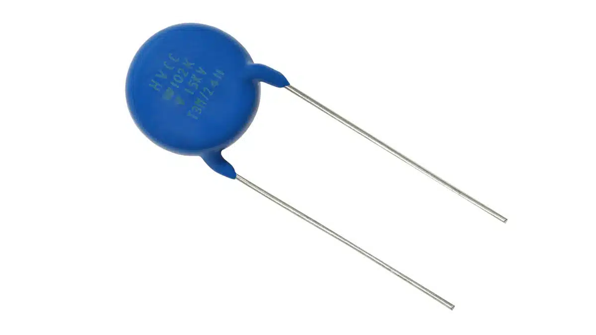
Vishay Roederstein HVCC Class 1 series capacitors feature capacitance loss of < 25 % at 15 kV, which is half that of Class 2 devices. In addition, their < 1.0 % DF at 1 kHz is 0.5 % lower. The result is reduced power losses and high reliability in high voltage generators for baggage scanners, medical and industrial X-ray applications, air purifiers and ionizers, and pulsed lasers.

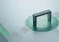
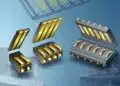
HVCC Class 1 series devices feature a capacitance range from 100 pF to 1 nF — with standard tolerances of ± 10 % — voltages of 15 kVDC, and an operating temperature range from -30 °C to +85 °C. The capacitors consist of a silver-plated ceramic disc with tinned copper-clad steel connection leads offering 0.65 mm and 0.80 mm diameters. The RoHS-compliant devices are available with straight leads with spacing of 9.5 mm and 12.5 mm, and feature an encapsulation made of flame-resistant epoxy resin in accordance with UL 94 V-0.

Samples and production quantities of the HVCC Class 1 series are available now, with lead times of 12 weeks.

FEATURES

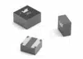
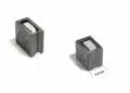
  • Ceramic singlelayer DC disc / AC disc capacitor
  • High reliability
  • High capacitance values up to 1 nF

APPLICATIONS

  • High voltage power supplies for x-ray sources and pulsed lasers
  • Baggage scanner
  • Medical x-ray

Related

Source: Vishay

Recent Posts

How to Manage Supercapacitors Leakage Current and Self Discharge 

1.10.2025
1

Qualification of Commercial Supercapacitors for Space Applications

1.10.2025
2

Experimental Evaluation of Wear Failures in SMD Inductors

1.10.2025
4

Resonant Capacitors in High-Power Resonant Circuits

1.10.2025
3
a Schematic diagram of the BNT-based components constructed based on the entropy-increase strategy. b Digital photograph, cross-sectional SEM image, and EDS mappings of the MLCCs. c Unipolar P-E loops of MLCCs as a function of applied E. d Wrec and η of the MLCCs as a function of applied E. The comparison of (e) Wrec and η, (f) η and UF of the MLCCs with those of other recently reported state-of-the-art MLCCs. source: Nature Communications

Researchers Proposed Enhanced Energy Storage MLCC

1.10.2025
2

Littelfuse Releases First Reflow-Compatible Illuminated Tactile Switch

1.10.2025
1

Vishay Unveils 5W Power Metal Strip Resistor in Compact 1206 Case Size

1.10.2025
2

Polymer Tantalum Capacitors Beyond AEC-Q200 LEO Satellites

30.9.2025
18

Components Thermal and Frequency Challenges in 6G Base Stations

30.9.2025
8

Development of Nitrogen-Doped Graphene Supercapacitors 

30.9.2025
6

Upcoming Events

Sep 30
September 30 @ 12:00 - October 2 @ 14:00 EDT

MIL-Std-883 TM 2010

Oct 8
11:00 - 12:00 CEST

PCB Online Shop – simply “Made in Germany” by Würth Elektronik

Oct 14
16:00 - 17:00 CEST

Smart Sensors, Smarter AI: Building Reliable Edge Systems

Oct 17
12:00 - 14:00 EDT

External Visual Inspection per MIL-STD-883 TM 2009

Oct 20
October 20 - October 23

Digital WE Days 2025 – Virtual Conference

View Calendar

Popular Posts

  • Buck Converter Design and Calculation

    0 shares
    Share 0 Tweet 0
  • Boost Converter Design and Calculation

    0 shares
    Share 0 Tweet 0
  • Flyback Converter Design and Calculation

    0 shares
    Share 0 Tweet 0
  • LLC Resonant Converter Design and Calculation

    0 shares
    Share 0 Tweet 0
  • Dual Active Bridge (DAB) Topology Explained

    0 shares
    Share 0 Tweet 0
  • SEPIC Converter Design and Calculation

    0 shares
    Share 0 Tweet 0
  • What is a Dielectric Constant and DF of Plastic Materials?

    4 shares
    Share 4 Tweet 0
  • Ripple Current and its Effects on the Performance of Capacitors

    3 shares
    Share 3 Tweet 0
  • MLCC and Ceramic Capacitors

    0 shares
    Share 0 Tweet 0
  • Flying Capacitors Explained

    0 shares
    Share 0 Tweet 0

Newsletter Subscription


Passive Components Blog

© EPCI - Leading Passive Components Educational and Information Site

  • Home
  • Privacy Policy
  • EPCI Membership & Advertisement
  • About

No Result
View All Result
  • Home
  • Knowledge Blog
  • Premium Suppliers

© EPCI - Leading Passive Components Educational and Information Site

This website uses cookies. By continuing to use this website you are giving consent to cookies being used. Visit our Privacy and Cookie Policy.
Go to mobile version