Passive Components Blog
No Result
View All Result
  • Home
  • NewsFilter
    • All
    • Aerospace & Defence
    • Antenna
    • Applications
    • Automotive
    • Capacitors
    • Circuit Protection Devices
    • electro-mechanical news
    • Filters
    • Fuses
    • Inductors
    • Industrial
    • Integrated Passives
    • inter-connect news
    • Market & Supply Chain
    • Market Insights
    • Medical
    • Modelling and Simulation
    • New Materials & Supply
    • New Technologies
    • Non-linear Passives
    • Oscillators
    • Passive Sensors News
    • Resistors
    • RF & Microwave
    • Telecommunication
    • Weekly Digest

    TDK Extends SMT Gate Drive Transformers to 1000 V

    Non-Linear MLCC Class II Capacitor Measurements Challenges

    Researchers Demonstrated HfO Anti-Ferroelectric Flexible Capacitors

    Connector Industry Achieves Double-Digit Growth

    Stackpole Unveils Metal Element High Current Chip Jumpers

    Common Mistakes in Flyback Transformer Specs

    Vishay Releases Miniature SMD Trimmers for Harsh Environments

    Würth Elektronik Releases Push-Button and Main Switches

    Littelfuse Unveils High-Precision TMR Angle Magnetic Sensors

    Trending Tags

    • Ripple Current
    • RF
    • Leakage Current
    • Tantalum vs Ceramic
    • Snubber
    • Low ESR
    • Feedthrough
    • Derating
    • Dielectric Constant
    • New Products
    • Market Reports
  • VideoFilter
    • All
    • Antenna videos
    • Capacitor videos
    • Circuit Protection Video
    • Filter videos
    • Fuse videos
    • Inductor videos
    • Inter-Connect Video
    • Non-linear passives videos
    • Oscillator videos
    • Passive sensors videos
    • Resistor videos

    Non-Linear MLCC Class II Capacitor Measurements Challenges

    Percolation Phenomenon and Reliability of Molded Power Inductors in DC/DC converters

    Root Causes and Effects of DC Bias and AC in Ceramic Capacitors

    How to Calculate the Output Capacitor for a Switching Power Supply

    Switched Capacitor Converter Explained

    Understanding Inductor Dot Markings and Their Application in LTspice

    Accelerating Full Bridge LLC Resonant Converter Design with Frenetic AI

    Understanding Switched Capacitor Converters

    Coupled Inductors Circuit Model and Examples of its Applications

    Trending Tags

    • Capacitors explained
    • Inductors explained
    • Resistors explained
    • Filters explained
    • Application Video Guidelines
    • EMC
    • New Products
    • Ripple Current
    • Simulation
    • Tantalum vs Ceramic
  • Knowledge Blog
  • Suppliers
    • Who is Who
  • Events
No Result
View All Result
Passive Components Blog
No Result
View All Result

What Filter S-Parameters Are Good For

4.1.2023
Reading Time: 4 mins read
A A

This blog article from Knowles Precision Devices explains what S-parameters can tell you about a filter’s performance and show an example of how to plot a filter’s S-parameters using a free open-source tool.

In general, we like to think of scattering parameters, commonly known as S-parameters, as the Swiss Army knife of RF data since this data can tell you quite a bit about the performance of a filter.

RelatedPosts

Knowles Unveils High-Performance Safety-Certified MLCC Capacitors

Knowles Releases Inductors for Mission-Critical RF Applications

Learn How Supercapacitors Enhance Power System in Knowles eBook

This is because an S-parameter file refers to the scattering matrix of a microwave network, which is a mathematical construct that quantifies how RF energy propagates through a linear multi-port network.

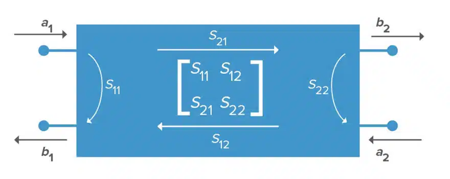
For a two-port network, the S-parameter matrix consists of four S-parameters – S11, S12, S21, and S22 –that define the relationships between the two ports in the RF system.

More specifically, these four S-parameters define the following elements in the bidirectional network:

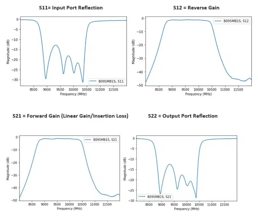
  • S11 – The reflection coefficient at the input, related to return loss
  • S12 – A transmission coefficient that defines reverse gain
  • S21 – Also a transmission coefficient that measures forward gain – in the case that the measurement ports have the same impedance, this is a measure of insertion loss
  • S22 – Also a reflection coefficient, defines output port reflection
Figure 1. A representation of an S-parameter matrix of a two-port RF device where a represents an input and b represents an output

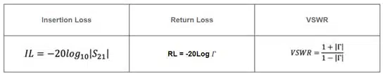
Using the S-parameters for a filter, you can calculate values for insertion loss, return loss, and voltage standing wave ratio (VSWR), which is a measure of the filter’s match to a given impedance, with the following equations:

Insertion Loss, Return Loss, VSWR expressed by S parameters

A Real-World Example of Plotting a Filter’s S-Parameters

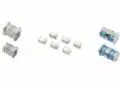
Let’s now look at an example of how to measure a filter’s performance using the S-parameter file for Knowles Catalog Filters, the B095MB1S, which is a 9.5 GHz surface mount bandpass filter. For the analysis in this example, we will use a free open-source tool, scikit-rf, which is based on the Python programming language, to plot the S-parameters.

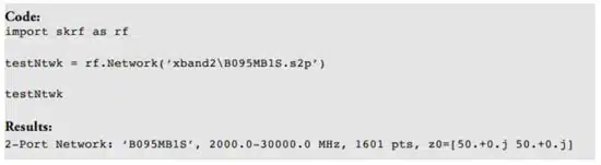
To access the S-parameter file for this filter (or any of our filters), just search for the filter on our website. Once you have the file, store it on your computer in a location where it is easy to access from within your Jupyter setup (which is a tool that makes it easier to write Python code interactively in a local web browser). We recommend renaming the file with a name that is easy to recognize. For our example, we put the file in a folder called ‘xband2’ and named the file ‘B095MB1S.s2p.’ Since Jupyter can see this folder, we can make a Network and review the Network properties. Below is the Python code we input in Jupyter to call this S-parameter file and create this example Network as well as the results.

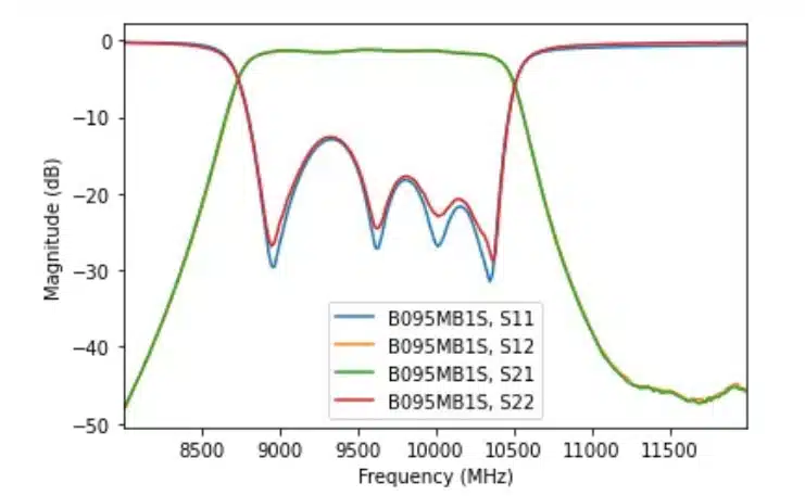
Note that in this example, the testNtwk is a Network object representing a two-port Network. The summary information in the results tells us the frequency range of this data set, the number of data points, and the impedance of the Network. The Network class also comes with convenient built-in methods for plotting and manipulating data. In this example, we can quickly plot the log-magnitude in decibels for the filter’s frequency range for four standard S-parameters by calling the plot s_db method, or we can plot each s-parameter individually (Figures 2 and 3).

Figure 2. All Four Filter S-parameters in one plot; source: Knowles Precision Devices

Figure 3. Each S Parameter plotted individually; source: Knowles Precision Devices

Related

Source: Knowles Precision Devices

Recent Posts

Non-Linear MLCC Class II Capacitor Measurements Challenges

19.8.2025
19

Researchers Demonstrated HfO Anti-Ferroelectric Flexible Capacitors

19.8.2025
12

Common Mistakes in Flyback Transformer Specs

15.8.2025
30

High Voltage MLCCs Meeting the Growing Demand for Efficiency in Power Conversion

12.8.2025
133

Radiation Tolerance of Tantalum and Ceramic Capacitors

8.8.2025
77

Percolation Phenomenon and Reliability of Molded Power Inductors in DC/DC converters

6.8.2025
45

Root Causes and Effects of DC Bias and AC in Ceramic Capacitors

6.8.2025
57

How to Calculate the Output Capacitor for a Switching Power Supply

6.8.2025
51

Additive Manufacturing of Mn-Zn Ferrite Planar Inductors

4.8.2025
28

Evaluation and Modeling of Supercapacitors for Reliability of Lifetime Predictions

4.8.2025
37

Upcoming Events

Aug 27
17:00 - 18:00 CEST

Capacitor Assemblies for High-Power Circuit Designs

Sep 3
15:30 - 17:30 CEST

How to Choose Your Magnetic Supplier

Sep 16
17:00 - 18:00 CEST

EMI Shielding Challenges

Sep 22
September 22 @ 13:00 - September 25 @ 15:15 EDT

Pre Cap Visual Inspection per Mil-Std-883 (TM 2017)

Sep 30
September 30 @ 12:00 - October 2 @ 14:00 EDT

MIL-Std-883 TM 2010

View Calendar

Popular Posts

  • Buck Converter Design and Calculation

    0 shares
    Share 0 Tweet 0
  • Boost Converter Design and Calculation

    0 shares
    Share 0 Tweet 0
  • Flyback Converter Design and Calculation

    0 shares
    Share 0 Tweet 0
  • LLC Resonant Converter Design and Calculation

    0 shares
    Share 0 Tweet 0
  • What is a Dielectric Constant and DF of Plastic Materials?

    4 shares
    Share 4 Tweet 0
  • Ripple Current and its Effects on the Performance of Capacitors

    3 shares
    Share 3 Tweet 0
  • Dual Active Bridge (DAB) Topology Explained

    0 shares
    Share 0 Tweet 0
  • How to Design an Inductor

    0 shares
    Share 0 Tweet 0
  • Core Materials, Permeability and Their Losses

    0 shares
    Share 0 Tweet 0
  • MLCC Case Sizes Standards Explained

    0 shares
    Share 0 Tweet 0

Newsletter Subscription


Passive Components Blog

© EPCI - Leading Passive Components Educational and Information Site

  • Home
  • Privacy Policy
  • EPCI Membership & Advertisement
  • About

No Result
View All Result
  • Home
  • Knowledge Blog
  • Premium Suppliers

© EPCI - Leading Passive Components Educational and Information Site

This website uses cookies. By continuing to use this website you are giving consent to cookies being used. Visit our Privacy and Cookie Policy.
Go to mobile version