


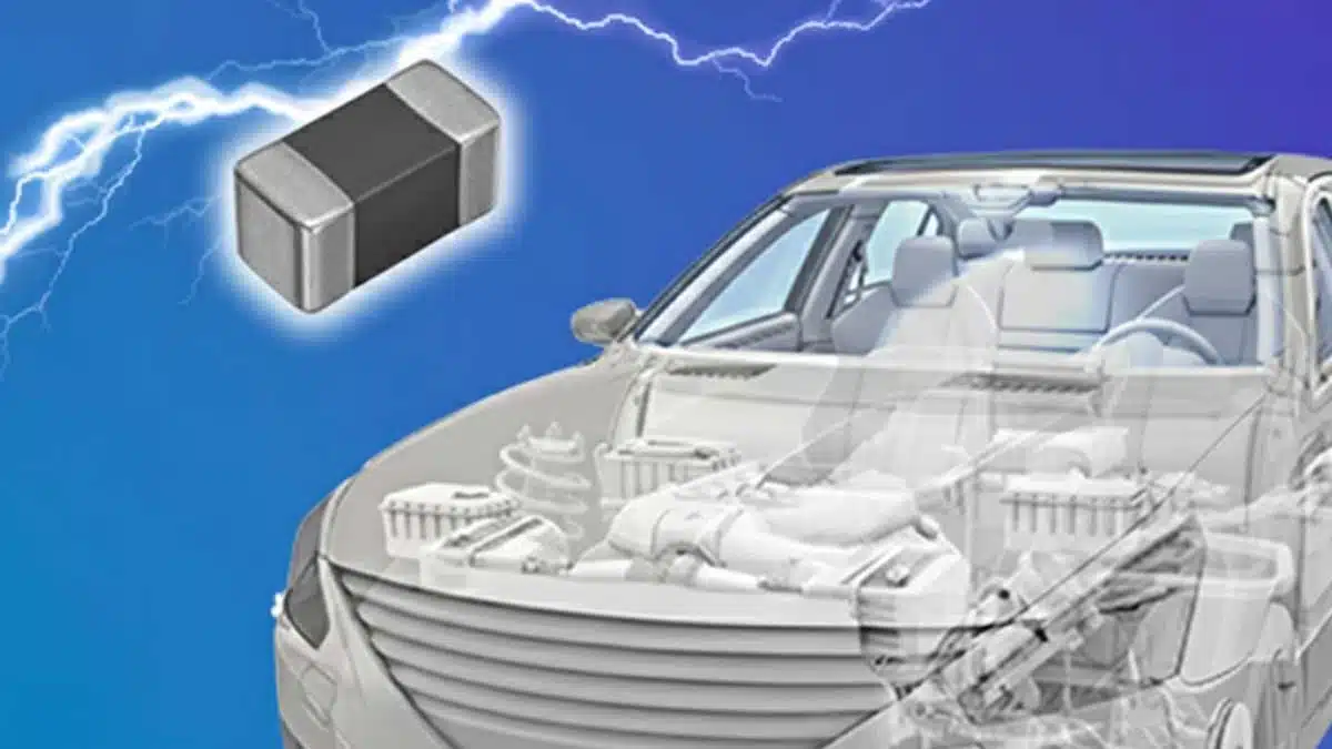
Automotive Ethernet, ADAS and telematics are pushing more high‑speed, space‑constrained interfaces into every ECU, making robust ESD protection a layout and BOM challenge. TDK’s AVRH series automotive chip varistors, including a new 0603 device, target exactly this problem as drop‑in alternatives to conventional TVS diodes in communication lines.
The series combines AEC‑Q200 qualification, high ESD robustness and very small footprints to support miniaturized, high‑density automotive electronics.
Key features and benefits
The AVRH series is an automotive‑grade lineup of multilayer chip varistors optimized for communication interfaces such as LIN and in‑vehicle Ethernet. It is qualified to AEC‑Q200 and is positioned as a compact, robust replacement for TVS diodes in ESD protection roles.
Key characteristics and benefits include:
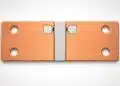
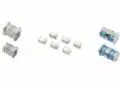
- Ultra‑compact sizes
- 1005 mm baseline size for automotive communication lines
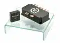
- New 0603 mm device AVRH06C270KT200NA7 as one of the smallest automotive chip varistors in this class
- Up to about 70–80% PCB area reduction versus typical TVS diodes with 1005 size, and up to about 85% reduction with the new 0603 size, enabling higher component density and smaller ECUs
- High ESD robustness
- Chip varistor structure based on zinc‑oxide ceramic with multilayer configuration designed for ESD and surge absorption
- AVRH series demonstrates no detectable degradation up to ±30 kV under IEC 61000‑4‑2 (150 pF / 330 Ω, 10 discharges per level, contact discharge) in internal evaluations
- Acceptance criteria for varistor stability are defined as a varistor voltage change ΔV1mA / V1mA within ±10%, allowing engineers to directly relate test data to long‑term stability
- Automotive‑grade reliability
- AEC‑Q200 compliance supports use in safety‑relevant automotive modules
- Maximum operating temperature up to 125 °C, suitable for typical cabin and many under‑dashboard and telematics locations
- Pr‑based varistor materials in the AVRH series provide improved stability under repeated ESD stress compared with traditional Bi‑based technologies
- Low capacitance for data lines
- Capacitance ranges in the tens of picofarads class (for example, about 10.5–19.5 pF and 24.5–45.5 pF typical ranges in key AVRH parts), suitable for LIN and many high‑speed communications where loading of the line must be limited
- Low capacitance simplifies signal‑integrity budgeting, especially in differential links and longer harness runs
- Cost and assembly advantages
- Miniaturization reduces PCB area and can enable fewer layers or smaller boards, which directly contributes to cost reduction at system level
- The ability to replace larger TVS diodes and legacy varistors helps consolidate footprints and standardize protection concepts across multiple ECUs
Typical applications
The AVRH series targets ESD and surge protection in automotive communication lines and small signal interfaces where space and reliability are critical. The new 0603 device AVRH06C270KT200NA7 is already being adopted in multiple in‑vehicle systems.
Representative application areas:
- Automotive microphones
- Protection of audio and voice‑recognition microphones against ESD from user interaction and cable coupling
- Noise suppression on small‑signal lines in hands‑free systems and in‑cabin voice interfaces
- Telematics and communication ECUs
- ESD protection for cellular, GNSS, and V2X communication modules, including external antenna feedlines and RF‑adjacent digital interfaces
- Protection of high‑speed serial interfaces inside telematics control units where PCB space is at a premium
- ADAS and sensor interfaces
- Protection of camera, radar and sensor communication lines in ADAS modules where connector areas are especially exposed to ESD events
- Use in high‑density control boards related to electric vehicles, where multiple sensor and communication channels compete for limited PCB area
- Infotainment and in‑vehicle networks
- ESD and surge protection for in‑vehicle Ethernet links such as 100BASE‑T1 and 1000BASE‑T1, and emerging standards like 10BASE‑T1S, where low capacitance and high robustness are essential
- Protection of LIN, CAN and other low‑ to mid‑speed buses in body electronics and comfort systems
In general, these chip varistors are suitable wherever a compact, robust protection element is needed close to the connector or component, especially in modules with strict space constraints.
Technical highlights
Chip varistors versus TVS diodes
Both chip varistors and TVS diodes are used for overvoltage and ESD protection, but their internal structures and failure behaviors differ, which has implications for design decisions.
- TVS diodes
- Silicon PN‑junction structures with very fast response to ESD events
- Typically exhibit abrupt failure (short circuit) at a defined stress level, often without gradual parametric drift
- Well established in many automotive platforms but often larger in footprint for a given voltage rating
- Chip varistors (AVRH)
- Polycrystalline zinc‑oxide ceramic body, often in multilayer form, tailored for high‑energy ESD absorption
- Designed for stable characteristics up to ±30 kV in IEC 61000‑4‑2 testing, with little change in varistor voltage
- When combined with Pr‑based material systems, can offer improved resistance to degradation under repeated ESD events compared with Bi‑based varistors
From a design perspective, the AVRH series provides a varistor‑type protection behavior with automotive qualification and dimensional advantages, making it attractive wherever PCB footprint and long‑term ESD stability are priorities.
Material system and ESD durability
See below the contrasts between Bi‑based and Pr‑based varistor materials and its benchmark.
- Bi‑based SMD varistors
- Historically derived from large disk‑type surge protectors
- In SMD form, they can show higher residual resistance after conduction, leading to more heat generation during ESD events
- Single high‑voltage ESD events can cause noticeable degradation in varistor voltage
- AVRH series (Pr‑based)
- Developed for high reliability in industrial and automotive use
- Demonstrates no measurable degradation in varistor voltage up to ±30 kV under IEC 61000‑4‑2 conditions in internal testing
- Evaluations against competitor Bi‑based and Pr‑based devices show that some competitor samples shorted at 30 kV, while AVRH devices continued to meet the varistor voltage stability criteria
For engineers, this means that AVRH varistors can be designed into communication lines with a comfortable margin against worst‑case ESD events, reducing risk of latent failures.
Representative part parameters
The application note highlights several AVRH parts used in comparison with competitor varistors and TVS diodes. Exact limits should always be confirmed in the latest manufacturer datasheet.
| Manufacturer / Series | Example part number | Typical use case | Varistor / Zener voltage (approximate V1mA or Vz ranges) | Capacitance range (C1 kHz) | DC rating (approximate max) |
|---|---|---|---|---|---|
| TDK AVRH series | AVRH10C220YT201MA8 | LIN protection | About 19–26 V varistor voltage according to datasheet | About 160–240 pF | About 16 V DC |
| TDK AVRH series | AVRH10C270KT150NA8 | Comms lines | About 24–30 V varistor voltage according to datasheet | About 10.5–19.5 pF | About 19 V DC |
| TDK AVRH series | AVRH10C270KT350NA8 | Comms lines | About 24–30 V varistor voltage according to datasheet | About 24.5–45.5 pF | About 19 V DC |
| TDK AVRH series | AVRH06C270KT200NA7 | 0603 miniaturized | Varistor and rating values according to manufacturer datasheet | Capacitance according to manufacturer datasheet | Automotive‑grade rating according to manufacturer datasheet |
These values show the typical trade‑off between capacitance and varistor voltage in devices optimized for common automotive interfaces such as LIN or low‑voltage communication lines.
Availability and part numbers
The AVRH series has been in mass production since 2019, with volumes projected to exceed hundreds of millions of units per month around 2025 according to TDK’s information. The series originally focused on 1005 mm automotive parts and has now been extended with an even smaller 0603 mm variant for extreme space constraints.
Key availability points:
- AVRH series overview
- Multiple part numbers covering different varistor voltages and capacitance values for communication and signal lines
- AEC‑Q200 compliant lineup providing second‑source capability to many existing 1608 and 1005‑based designs
- New 0603 device AVRH06C270KT200NA7
- Developed as the smallest model in the AVRH series, targeting high‑density communication boards and modules
- Pre‑mass‑production datasheet and a communication‑line design‑in guide for EMI filters and ESD protection can be obtained via a web form (datasheet access is gated and provided directly by TDK)
- Sample and distribution
- Free sample campaigns are periodically offered via TDK’s contact forms, with regional and customer‑type limitations
- Standard production parts in the AVRH series are available through TDK’s authorized distributors and can be located via the distributor search tool
When designing‑in, engineers should obtain the latest datasheets and any product change notifications directly from TDK or authorized channels to ensure alignment with current specifications.
Design‑in notes for engineers
From a practical design perspective, migrating from TVS diodes or legacy varistors to AVRH chip varistors impacts layout, EMC behavior and qualification strategies. The following points can help streamline the design‑in process.
Electrical selection
- Match system voltage and interface type
- Select varistor voltage and DC rating in line with the nominal bus voltage and maximum transient levels for the targeted interface (for example LIN, CAN subnet, Ethernet PHY side)
- Ensure that the clamping characteristics of the chosen AVRH part keep the line within the absolute maximum ratings of the transceiver or ASIC under IEC 61000‑4‑2 testing
- Consider line capacitance budget
- For high‑speed differential lines, include the AVRH device’s capacitance in the overall channel model, particularly on long harnesses or multi‑drop networks
- Use the lower‑capacitance AVRH variants where eye diagrams are tight, and reserve higher‑capacitance parts for slower or more robust single‑ended lines
- Evaluate ESD and surge behavior
- Validate protection in both system‑level (IEC 61000‑4‑2) and any OEM‑specific test pulses or HBM/CDM schemes required for the application
- Pay attention to failure mode: the AVRH series is positioned to avoid sudden short‑circuit failures up to ±30 kV in internal testing, helping improve system‑level robustness
PCB layout and footprint migration
- Replacing TVS diodes with AVRH varistors
- When migrating from discrete TVS diodes, designers can typically shrink the protection footprint by roughly 70–80% using 1005 AVRH parts, and up to around 85% with the 0603 AVRH06C270KT200NA7
- This footprint reduction can be used either to shrink the PCB, add redundant protection devices, or improve routing margins around critical connectors
- Placement guidelines
- Place AVRH devices as close as possible to the connector or ESD entry point, with a short, low‑inductance path to the reference ground
- Combine with robust ground pattern design: solid ground planes, short vias and adequate stitching help ensure that ESD current is diverted away from sensitive circuitry
- Thermal and mechanical considerations
- With maximum operating temperature up to 125 °C, AVRH devices can be placed in typical automotive ECU environments, but local self‑heating under repeated surge events should still be considered during worst‑case testing
- For 0603 packages, pay attention to solder pad dimensions and reflow profiles to avoid mechanical stress cracking, especially on rigid or large boards
System‑level qualification
- Automotive qualification
- Use the AEC‑Q200 qualification status of the AVRH series as a basis for component qualification within the ECU, but ensure that the specific part number and factory match OEM requirements
- System‑level tests such as ESD, surge and burst immunity should be re‑run after migration from TVS diodes to AVRH varistors due to the different clamping and dynamic behavior
- Documentation and simulation
- Take advantage of TDK’s design‑in guides and any available simulation tools for surge and ESD protection to shorten evaluation cycles
- Maintain internal documentation on the chosen varistor voltage and capacitance variants to support future platform reuse and second‑source strategies
Conclusion
TDK’s AVRH automotive chip varistor series offers an attractive migration path away from conventional TVS diodes for ESD protection in space‑constrained automotive communication lines. With AEC‑Q200 qualification, high ESD robustness up to ±30 kV in testing, and new 0603‑size variants, the series enables high‑density packaging without sacrificing reliability. For design engineers and purchasing teams, it provides a scalable, miniaturized platform for harmonizing ESD protection strategies across ADAS, telematics, infotainment and other vehicle domains.
Source
This article is based on TDK’s application note on high‑density packaging enabled by automotive chip varistors as TVS diode replacements, complemented with explanatory context and interpretation for design engineers and component purchasers.
References
- TDK application note: High‑Density Packaging Enabled by Automotive Chip Varistors as TVS Diode Replacements (AVRH series, automotive 0603 chip varistor)
- TDK AVRH series product overview and parametric search
- TDK overview: What is the difference between Zener/TVS diodes and varistors?
- TDK application note: Chip Varistors Prevent Damage of Electronics from Electrostatic Discharge