


The article discuses design considerations and applications of capacitors for crossover audio circuits.
Capacitors have a broad range of applications in audio circuits and systems. One of the main subsystems of a typical audio system is a crossover network. A crossover network is used to separate an audio signal into different frequency-dependent components. The separated components are then sent to specific driver circuits and speakers. The placement of this circuit can vary depending on the design of an audio system.
Capacitors are key components in virtually all types of crossover networks. Other passive components that are essential in these networks include resistors and inductors. For this article, we will primarily focus on the role of capacitors and the types that are commonly used in crossover networks. The article will also explore some of the key considerations when designing crossover circuits.
Key Takeaways
- The article discusses design considerations for audio capacitors in crossover networks.
- Capacitors play a crucial role in separating audio signals for optimal frequency performance.
- Common capacitor types include film capacitors, which offer low loss and reliability, while non-polar electrolytics may be used in less critical areas.
- Design examples illustrate practical capacitor selection for hi-fi and PA systems to ensure sound quality and stability.
- Well-designed crossover networks enhance performance by allowing drivers to operate within their optimal frequency ranges.
Why the components of an audio signal are separated
The audio frequency ranges between approximately 20 Hz and 20 kHz. Although this frequency range can be handled by a single driver, such a configuration does not yield optimum sound output. Using a single driver usually results in distorted and low quality sound output.
Similarly, a low quality sound output is obtained when a single speaker is used for the entire audio frequency. To prevent signal distortion in audio systems, most of today’s speakers are designed to operate optimally for a specific audio frequency range. This means that a combination of different speakers is required for optimum performance of an audio system.
For a full range loudspeaker, the frequency range is usually characterized by unsatisfactory bass and treble. The frequency response for such a system usually has an irregular frequency response. Due to this poor performance of full-range speakers, they are rarely used in high performance audio systems.
Using a single diaphragm for both bass and treble makes it difficult to lower distortion in an audio system. This characteristic makes full-range audio devices unsuitable for systems in which high quality output is desired.
The design of a diaphragm has a significant effect on the quality of the sound produced by a loudspeaker. To start with, low frequencies are known to introduce harmonic distortion in the diaphragm. The low frequencies also cause inter-modulation between treble and bass.
The distortion caused by low frequencies can be reduced by decreasing diaphragm excursion. This requires the diaphragm area to be increased. High frequency reproduction worsens with an increase in the size of a loudspeaker. To overcome these challenges, it is necessary to separate the components of an audio signal into different components and use audio devices that are optimized for limited audio frequency ranges.
Design Considerations for Crossover Networks
Crossover networks are essential components in most of today’s audio systems. In a typical audio system, a crossover network is inserted after the amplifier. It separates and sends the high frequency components to the tweeter, the bass audio signals to the woofer, and the mid-range components to the mid-range speakers.
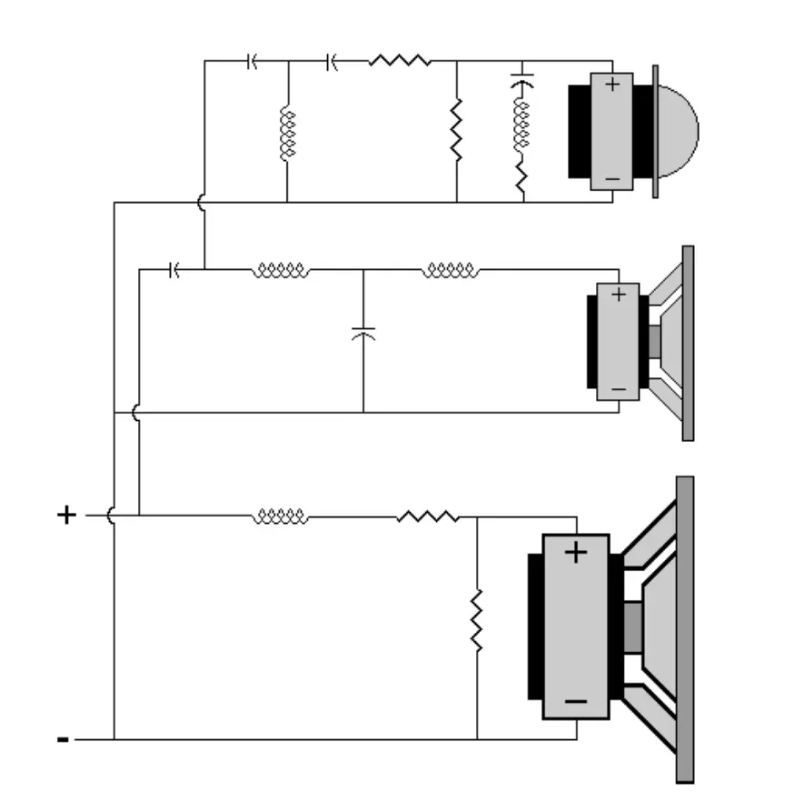
Filters, low pass and high pass, are the building blocks of crossover networks. These sub-circuits consist of capacitors, resistors and inductors in different configurations. These passive components are selected and configured depending on the frequency range of the audio component.
A low pass filter allows low frequency components of an audio signal to pass while blocking high frequency components. On the other hand, a high pass filter blocks both the low frequency and mid-range frequency components while allowing the high pass components to pass.
Although various passive components are used in a crossover network, the overall performance of a circuit is mainly determined by the capacitors used. In most crossover networks, inductors and resistors of fixed values are used.
Furthermore, there is no need to replace these passive components (inductors and resistors) when upgrading a network. The only time replacement is needed is when a component is damaged.
Choosing Capacitors for Crossover Networks
Role of Capacitors in Crossover Networks
In passive loudspeaker systems the crossover network splits the full‑band audio signal into narrower ranges that are routed to drivers optimized for bass, midrange and treble reproduction. Capacitors, together with inductors and resistors, implement the high‑pass and low‑pass sections that define crossover frequency, filter order and damping, and their non‑ideal properties have a direct impact on frequency response, distortion and long‑term stability.
From the amplifier’s point of view the crossover is a reactive load placed after the power stage, so the capacitors operate with significant AC voltage and current at audio frequencies rather than with DC bias. Parameters such as equivalent series resistance (ESR), dielectric absorption (DA), insulation resistance and susceptibility to microphonics therefore become key selection criteria in addition to nominal capacitance and voltage rating.
Electrical Stresses and Design Targets
A structured capacitor choice starts with estimating the electrical stresses in the crossover:
- Maximum RMS and peak AC voltage across each capacitor at rated amplifier power and typical loudspeaker impedance
- Expected audio spectrum and crest factor in the intended application (home hi‑fi, studio, PA)
- Ambient temperature inside the loudspeaker enclosure and additional self‑heating due to ESR
- Required lifetime and acceptable drift of capacitance and loss parameters
In home hi‑fi systems with amplifiers up to a few hundred watts, crossover capacitors usually see AC voltages of a few tens of volts RMS, with occasional higher peaks. A practical rule is to select capacitors with at least 2× the maximum expected RMS voltage across the component, which provides sufficient headroom for musical transients and production tolerances without excessive overspecification.
Ripple current through the capacitor depends on the filter topology and driver impedance, and must remain within the manufacturer’s rating for the expected operating temperature. ESR and dissipation factor determine power loss , and thus the internal temperature rise that strongly influences lifetime. In high‑power PA systems, where average levels are much higher than in domestic applications, larger case sizes, lower‑ESR technologies and more generous voltage/current margins are needed.
Capacitor Technologies for Crossover Use
Electrolytic Capacitors
Aluminium electrolytic capacitors come in a variety of designs but they are not widely used in audio applications. Aluminium and non‑polar electrolytic capacitors provide high capacitance at low cost and are sometimes used in woofer sections where large values are required and distortion sensitivity is lower. However, their relatively high ESR and dissipation factor lead to higher self‑heating at audio frequencies, and their parameters drift over time with temperature and applied voltage, so they are not ideal for critical signal‑path positions. When they are used, the designer must check ripple‑current capability, ESR and specified lifetime at the estimated enclosure temperature to avoid premature failure.
Ceramic Capacitors
Ceramic capacitors are ubiquitous in audio electronics but are rarely suitable in passive crossovers. Many high‑K ceramic dielectrics show strong voltage‑dependent capacitance, relatively high DA and pronounced microphonic behaviour, converting cabinet vibrations into unwanted electrical signals that can modulate the audio. Their frequency response, insulation resistance and ESR characteristics are generally inferior to those of film capacitors in the audio band, which limits their use to auxiliary roles rather than as main crossover elements.
Film Capacitors
Film capacitors are the primary choice for quality crossover networks because they combine low ESR, low DA, high insulation resistance and good stability over time and temperature. Metallized polypropylene film provides an excellent balance of loss, size and cost, and is widely used in series paths of midrange and tweeter sections, while foil or stacked‑film versions can be reserved for the most critical positions where minimum loss and highest linearity are required. When appropriately mounted and mechanically damped, film capacitors also offer lower sensitivity to microphonics than ceramic or electrolytic types.
Tantalum and Niobium Oxide
Tantalum and niobium oxide capacitors offer compact, stable capacitance values and are attractive in tightly constrained portable audio designs, but their polar nature complicates their use in passive crossovers carrying largely AC signals. Incorrect biasing can lead to degradation or failure, so they are generally avoided in conventional loudspeaker crossovers and reserved for specialized miniature systems where bias and operating conditions are strictly controlled.
Practical Selection Guidelines
In typical home hi‑fi or studio monitors, film capacitors are recommended in all series signal paths of tweeter and midrange sections, where low DA and low ESR directly translate into reduced distortion and stable high‑frequency response. Metallized polypropylene types with voltage ratings of 100 V AC or 250 V DC and tolerances of ±5% are a common choice, while very high‑end designs may use foil‑type capacitors in the most sensitive positions.
In woofer shunt positions and impedance‑equalization networks, non‑polar electrolytics can be considered to achieve larger values at acceptable cost and volume, provided their ripple‑current rating, ESR and lifetime are verified for the expected operating temperature. Designers of high‑power PA systems should give priority to film capacitors even in shunt positions because their lower loss and better thermal behaviour reduce the risk of overheating during sustained high‑level operation.
Layout and mechanical mounting also affect performance: keeping current loops compact, avoiding tight coupling between high‑current inductors and signal capacitors, and mechanically securing and damping larger film capacitors all help to minimize induced noise and microphonic effects. Capacitors should be placed away from hot components such as power resistors and arranged to promote airflow, which improves reliability by limiting operating temperature.
Capacitor Location Guidelines in Crossover Networks
Even when the same dielectric technology is used, the location of a capacitor in the crossover strongly influences both its electrical stress and its audible impact. The following guidelines help align part selection and derating with the role each capacitor plays in the network.
Series capacitors in tweeter and midrange paths
Series elements in the HF and upper‑mid bands are the most sonically critical positions because any non‑linearity or drift directly modulates the program signal.
- Use polypropylene film capacitors (metallized or film‑foil) in all series signal paths feeding tweeters and midrange drivers.
- Prefer tighter tolerances (±5% or better) to keep the electrical and acoustic crossover close to the design target.
- Specify generous voltage margin (at least 2× the maximum expected RMS voltage in hi‑fi, higher for PA) and low ESR at the crossover frequency to minimize loss, heating and distortion.
- In high‑power systems, split the required value into two or more parallel film capacitors to share ripple current and reduce individual temperature rise.
Shunt capacitors across woofers and midranges
Capacitors used in low‑pass sections and impedance‑equalization networks typically see higher currents but are somewhat less sensitive from a subjective distortion standpoint than series HF parts.
- In high‑quality hi‑fi and studio monitors, film capacitors are still preferred for woofer and midrange shunt positions to ensure stable response and low loss over lifetime.
- In cost‑sensitive designs, non‑polar electrolytics can be used in these shunt locations if their ESR, ripple‑current rating, voltage rating and lifetime are verified for the enclosure temperature.
- For mixed solutions, a larger NP electrolytic can be paralleled with a small polypropylene film “bypass” capacitor (for example 1–2.2 µF) to improve high‑frequency behaviour while keeping volume and cost under control.
Capacitors in protection and attenuation networks
L‑pads, protection circuits for HF drivers and shaping networks often contain relatively small capacitors whose failure or drift can significantly change tonal balance or driver stress.
- Use film capacitors for all capacitors in HF protection and attenuation networks, even when capacitance values are modest.
- Ensure that voltage rating and surge capability cover worst‑case conditions such as amplifier clipping and feedback oscillation; PA systems in particular benefit from higher AC ratings and robust case sizes.
- Place these capacitors where they are mechanically secure and not exposed to direct vibration from the cabinet walls or drivers to limit microphonic effects.
Physical placement and thermal environment
Besides the schematic location, the physical location of capacitors on the crossover board affects reliability and, in some cases, perceived sound quality.
- Keep high‑current loops compact and avoid placing small‑signal or tweeter‑path capacitors directly next to large inductors or power resistors.
- Position capacitors away from hot components and cabinet hot‑spots; where possible, orient larger film cans to allow airflow around them and secure them mechanically with clamps or adhesive to minimize vibration.
- Avoid tightly bundling wiring carrying high‑level low‑frequency currents with the leads of HF series capacitors to reduce inductive and capacitive coupling between bands.
| Crossover location | Recommended technology | Typical tolerance | Voltage / stress guideline |
|---|---|---|---|
| Tweeter series high‑pass | Polypropylene film (MKT/MKP, foil) | ±5% or better | ≥ 2× max RMS, low ESR at crossover frequency |
| Midrange series (band‑pass high‑pass leg) | Polypropylene film | ±5…10% | ≥ 2× max RMS, consider paralleling for high power |
| Woofer/mid shunt low‑pass | Film preferred, NP electrolytic possible | ±10…20% | Check ripple current, ESR, lifetime at cabinet temperature |
| Zobel and impedance‑equalization networks | Film for HF, NP electrolytic acceptable for LF | ±10…20% | Ensure stable ESR and value over frequency and ageing |
| HF protection and shaping networks | Polypropylene film | ±5…10% | Robust AC rating for clipping and transients |
| Position in 2‑way hi‑fi speaker | Good choice | Better / best choice |
|---|---|---|
| Tweeter series high‑pass | Polypropylene film, ±10% | Polypropylene film, ±5%, foil type if budget allows |
| Midrange / small 3‑way series | Polypropylene film, ±10% | Polypropylene film, ±5%, higher voltage margin |
| Woofer shunt low‑pass | NP electrolytic, checked ESR & ripple | Metallized polypropylene film, larger case size |
| Zobel / impedance EQ | NP electrolytic with small film bypass | All‑film network, polypropylene parts |
| HF protection / shaping caps | Generic film capacitor | Polypropylene film with tight tolerance |
Note: NP electrolytic capacitors: Non‑polar / bipolar aluminium electrolytics are built as two standard polarized elements connected back‑to‑back inside one can, so they can handle AC without a defined +/− terminal. They are sold specifically for audio coupling and crossover use.
Design Example #1: 2‑Way Hi‑Fi Crossover at 2.5 kHz
This section illustrates a practical capacitor selection process for a 2‑way home hi‑fi loudspeaker with an 8 Ω woofer and 8 Ω tweeter and a nominal crossover frequency of 2.5 kHz. The power amplifier is specified for 100 W into 8 Ω, corresponding to approximately 28.3 V RMS at full output.
Target Electrical Specification
- Topology: 2nd‑order Linkwitz‑Riley (LR2) high‑pass for the tweeter, 2nd‑order LR2 low‑pass for the woofer
- Crossover frequency:
- Nominal load impedance:
- Maximum operating level: 100 W into 8 Ω (28.3 V RMS)
- Application class: Home hi‑fi, emphasis on low distortion and stable response
The ideal first‑order high‑pass capacitor value for an 8 Ω load at 2.5 kHz is approximately
For a 2nd‑order Linkwitz‑Riley (realized as cascaded Butterworth sections), each reactive element is scaled from the simple first‑order value by a factor determined by the filter prototype. In practice, designers typically arrive at series capacitor values in the range of 6.8 µF to 10 µF for tweeter sections at 2.5 kHz with 8 Ω drivers, depending on the chosen alignment and driver response.
Tweeter High‑Pass Section
A common implementation of the LR2 high‑pass uses a series capacitor followed by a shunt inductor across the tweeter. For the specified conditions, a suitable starting value for is 8.2 µF, a standard value close to the calculated 8 µF.
Capacitor technology choice:
- Type: Metallized polypropylene film capacitor
- Capacitance: 8.2 µF, tolerance ±5%
- Voltage rating: 100 V AC or 250 V DC (≥ 2× maximum 28.3 V RMS across the tweeter section)
- Target ESR at 2.5 kHz: < 50 mΩ
Metallized polypropylene provides low dissipation factor, low DA and stable capacitance over time, making it suitable for the critical series position in the tweeter path. For very high‑end applications, a foil‑type film capacitor of similar value can be considered to further reduce losses at the expense of increased volume and cost.
Woofer Low‑Pass Shunt Capacitor
On the woofer side, the 2nd‑order LR2 low‑pass is often implemented with a series inductor followed by a shunt capacitor across the woofer terminals. The first‑order approximation again yields around 8 µF, with practical values for typically between 6.8 µF and 12 µF depending on the chosen alignment and interaction with the woofer’s own roll‑off.
The shunt capacitor in the woofer low‑pass sees significant current at and above the crossover frequency, but the distortion sensitivity is somewhat lower than in the tweeter series path.
Capacitor technology options:
- Preferred: Metallized polypropylene film, 8.2 µF, 100 V AC or 250 V DC, for lowest loss and best linearity
- Cost‑optimized: Non‑polar electrolytic capacitor in the 8.2 µF to 10 µF range, with low ESR and adequate ripple‑current rating at enclosure temperature
If a non‑polar electrolytic is selected, the designer must verify that its ESR and dissipation factor do not lead to excessive self‑heating at the expected power levels, and that lifetime at the estimated operating temperature meets the system requirements. In higher‑end hi‑fi systems, a film capacitor is typically retained in this location despite the larger size to ensure long‑term stability and low distortion.
Voltage and Current Margining
At full amplifier power of 100 W into 8 Ω, the RMS current through the tweeter branch is on the order of 3.5 A, while the voltage across the series capacitor is a fraction of the total amplifier output, depending on frequency and driver impedance. Selecting capacitors with at least 2× voltage margin and sufficient ripple‑current capability ensures that the maximum internal temperature rise remains within the manufacturer’s ratings. For home hi‑fi use, where average listening levels are well below the 100 W peak rating, this margin provides additional robustness against occasional high‑level transients.
Summary of Example Values
| Crossover element | Role | Typical value range | Recommended technology |
|---|---|---|---|
| Tweeter series HP | 6.8–10 µF | Metallized polypropylene film | |
| Woofer shunt LP | 6.8–12 µF | Film (hi‑fi) or non‑polar electrolytic (cost) |
These component values and technologies form a practical starting point for a 2.5 kHz, 2‑way, 8 Ω crossover. Final values are typically fine‑tuned based on measured driver responses, target acoustic slopes and listening evaluations.
Design Example #2: 2‑Way PA Crossover at 1.6 kHz, 4 Ω, 500 W
This example considers a 2‑way professional PA loudspeaker using a 4 Ω woofer and a 4 Ω compression‑driver/horn, with a nominal crossover frequency of 1.6 kHz and an amplifier rated for 500 W into 4 Ω. The system is intended for continuous high sound‑pressure levels, so thermal management, reliability and voltage/current margins are more critical than in home hi‑fi use.
Target Electrical Specification
- Topology: 2nd‑order Linkwitz‑Riley (LR2) high‑pass for HF, 2nd‑order LR2 low‑pass for LF
- Crossover frequency:
- Nominal load impedance:
- Amplifier rating: 500 W into 4 Ω → approx. 44.7 V RMS at full power
- Application class: High‑power PA, emphasis on robustness and controlled distortion
The simple first‑order high‑pass capacitor value for a 4 Ω load at 1.6 kHz is
For a 2nd‑order LR alignment, practical series capacitor values for the HF section will typically fall near 20–27 µF, depending on the exact filter realization and the horn/driver response.
HF High‑Pass Capacitor Selection
The HF high‑pass is realized as a series capacitor followed by a shunt inductor across the compression driver. This capacitor is in the most critical signal path and also experiences high AC voltage and current during operation.
Capacitor selection:
- Capacitance: 22 µF (standard E12 value close to 25 µF)
- Technology: Metallized polypropylene film, or parallel combination of two 10 µF + one 2.2 µF to achieve required value and current sharing
- Voltage rating: ≥ 250 V AC or 400 V DC to ensure ample margin over 44.7 V RMS and transient peaks
- ESR at 1–5 kHz: As low as practical (tens of milliohms) to minimize loss and heating
Using multiple film capacitors in parallel reduces effective ESR and distributes ripple current, which lowers self‑heating and improves reliability under continuous high‑level operation. The use of polypropylene film maintains low DA and low distortion, which is important in the audibly sensitive mid‑ and high‑frequency range.
LF Low‑Pass Shunt Capacitor
On the LF side, the 2nd‑order low‑pass includes a shunt capacitor across the woofer following a series inductor. The capacitor sees substantial current near and above the crossover frequency, and its losses directly contribute to temperature rise in the crossover network.
Capacitor selection options:
- Capacitance: Typical starting range 22–33 µF, refined according to the woofer’s response and target acoustic slope
- Preferred technology for premium PA: Metallized polypropylene film, possibly implemented as several smaller units in parallel (e.g. 3 × 10 µF) to spread current and heat
- Cost‑constrained option: High‑quality non‑polar electrolytic capacitors with low ESR and high ripple‑current rating, possibly bypassed by a small polypropylene film (e.g. 1–2.2 µF) to improve high‑frequency behaviour
In high‑duty PA applications, even shunt positions benefit from film capacitors because their lower ESR and better thermal behaviour reduce the risk of overheating. If non‑polar electrolytics are used, they should be selected with generous voltage and temperature margins and positioned to allow adequate cooling.
Voltage, Current and Thermal Margins
At 500 W into 4 Ω, the RMS current through the loudspeaker is approximately 11.2 A, and both HF and LF branches can experience substantial currents in their respective pass‑bands. Capacitors should therefore be specified with:
- Voltage rating at least 3× the maximum RMS voltage expected across the element in normal use
- Ripple‑current ratings compatible with continuous high‑level operation at the enclosure’s internal ambient temperature
- Case sizes and mounting arrangements that promote heat dissipation
Using multiple film capacitors in parallel for each key position allows the designer to divide the total ripple current between units, reducing the thermal stress on each capacitor and improving overall reliability. Thermally critical components should be located away from hot power resistors and given mechanical support that also facilitates airflow around the bodies.
Summary of PA Example Values
| Crossover element | Role | Typical value range | Recommended technology |
|---|---|---|---|
| HF series high‑pass | 20–27 µF | Polypropylene film (often paralleled units) | |
| LF shunt low‑pass | 22–33 µF | Film (preferred) or high‑grade NP electrolytic |
These values and technologies form a robust starting point for a 1.6 kHz, 2‑way, 4 Ω, 500 W PA crossover. Final component values are typically optimized using measured driver data, target coverage and power‑handling requirements, and real‑world endurance testing.
How to choose capacitors for a 2‑way loudspeaker crossover
- Step 1 – Define crossover frequency and load impedance
Decide on the electrical crossover frequency based on the drivers’ usable ranges (for example 2.0–2.5 kHz for many dome tweeters and mid‑woofers).
Note the nominal impedance of each driver (typically 4 Ω or 8 Ω) because capacitance depends directly on this value. - Step 2 – Estimate capacitor values
Use a simple first‑order approximation to get a starting value for the series high‑pass capacitor. For common 2–3 kHz crossovers with 8 Ω drivers you will typically end up in the 6.8–10 µF range for the tweeter series capacitor and similar values for woofer shunt capacitors.
- Step 3 – Select capacitor technology by position
Use polypropylene film capacitors for all series signal paths (especially tweeters and upper midrange) to minimize loss and distortion. In less critical shunt positions where large values are needed, consider non‑polar electrolytics with suitable ripple‑current rating and, if required, a small film bypass capacitor to improve high‑frequency behaviour.
- Step 4 – Check voltage and current ratings
Estimate the maximum amplifier output (RMS voltage into the nominal load) and select capacitors with at least 2× that RMS voltage rating for hi‑fi use and higher margins for PA.Verify that the ripple‑current rating and thermal performance of the chosen capacitors are adequate for the intended power level and enclosure temperature.
- Step 5 – Verify and fine‑tune in measurements and listening tests
Measure the resulting electrical and acoustic responses and adjust capacitor values slightly to achieve the target crossover frequency and slope with the real drivers.
Confirm that the chosen capacitors remain cool in normal use and that the subjective balance and detail meet the design goal.
Conclusion
Well‑designed crossover networks are essential for extracting high performance from loudspeaker systems, because they allow each driver to operate within the frequency range where it performs best while maintaining controlled overall response and low distortion. Capacitors play a central role in these networks, and their non‑ideal parameters—ESR, dielectric absorption, insulation resistance and microphonic behaviour—directly shape both sound quality and long‑term stability.
For most hi‑fi, studio and PA applications, film capacitors, particularly metallized polypropylene, offer the most attractive combination of low loss, linearity and reliability, and are therefore preferred in all critical series and many shunt positions. Non‑polar electrolytic capacitors can still be used effectively in less sensitive locations where large values are required and their ripple‑current capability, ESR and lifetime have been carefully verified. The design examples presented for 2‑way hi‑fi and PA crossovers demonstrate how these technology choices, together with appropriate voltage and current margins, can be translated into practical component selections for real‑world systems.
FAQ
Capacitors in a passive crossover form high‑pass and band‑pass filters that direct high and mid frequencies to the appropriate drivers while blocking low‑frequency energy that would overload them.
For most hi‑fi, studio and PA loudspeakers, polypropylene film capacitors are preferred in critical signal paths because they offer low ESR, low dielectric absorption and stable parameters over time and temperature.
Non‑polar electrolytics can be used in woofer shunt positions or impedance‑equalization networks where large capacitance values are required and distortion sensitivity is lower, provided their ripple‑current rating, ESR and lifetime are adequate.
A common guideline is to choose capacitors with at least twice the maximum expected RMS voltage across the component in use, and considerably more in high‑power PA systems, to avoid overstress and premature failure.
Yes. Tolerances of ±5% for film capacitors typically keep electrical crossover points close to the design target, while wider tolerances may shift the acoustic crossover and require compensation in measurements or listening tests.
Electrically it is usually possible, but the lower ESR of film capacitors may change filter damping and tonal balance; in some restorations it is better to match the original ESR or simulate it with a small series resistor.
References
- Passive Components Blog – Choosing Capacitors for Crossover Audio Circuits
https://passive-components.eu/choosing-capacitors-for-crossover-audio-circuits - Electrocube – Capacitors in Audio/Speaker Crossover Networks
https://www.electrocube.com/pages/capacitors-in-audio-crossover-networks-data-sheet - RayPCB – Audio Capacitor Guide: Coupling, Bypass & Crossover Selection
https://www.raypcb.com/audio-capacitor/ - Specac / Specialist Components – Film Capacitor Selection Guide
https://specap.com/resources/guides/film-capacitor-selection - SoundImports – The Basics of Crossover Components
https://www.soundimports.eu/en/blogs/blog/the-basics-of-crossover-components/