


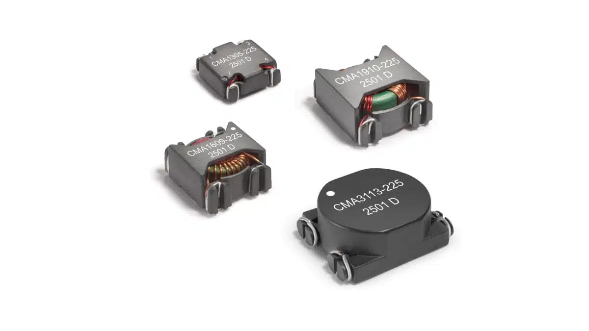
Coilcraft’s CMA family is a series of automotive‑qualified surface‑mount common mode chokes designed for EMI suppression in high‑current power line applications.
They target compact inverters, motor drives, onboard chargers, telecom and industrial supplies where high isolation and robust thermal performance are critical.
Key features and benefits
The CMA series is positioned as a high‑isolation, AEC‑Q200 qualified common mode choke family for power electronics where conducted EMI limits are tightening and available PCB area is at a premium.
Key characteristics include:
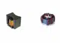
- Automotive qualified (AEC‑Q200) surface‑mount toroidal construction.
- High frequency common mode noise suppression up to 100 MHz.
- Isolation (hipot) rating of 1500 Vrms between windings.
- Excellent current ratings up to 8.2 A rms depending on case size and inductance value.
- Broad range of common mode impedances and inductance values per winding.
- Ferrite core material for high permeability and stable high‑frequency performance.
- Moisture Sensitivity Level 1, suitable for standard SMT processes and washing.
For design engineers, the combination of high isolation, high common‑mode impedance and SMT packaging simplifies meeting safety and EMC requirements without resorting to bulky through‑hole magnetics.
Typical applications
The CMA series is dedicated for automotive and general power line filtering tasks where common‑mode noise must be attenuated on AC or DC supply rails.
Typical use cases include:
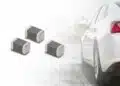
- Automotive inverters and traction motor drives on HV or LV bus lines.
- Onboard chargers in EV/HEV platforms, particularly on AC input and DC output lines.
- Automotive 12 V and 48 V power distribution modules and auxiliary converters.
- Telecom and datacom power systems requiring 1500 Vrms isolation.
- Industrial power supplies and motor drives with stringent conducted EMI limits.
- Consumer electronics power adapters where high isolation and compact toroidal SMT parts are desired.
In these applications, the choke is typically placed in series with the supply and return conductors (two lines) to block common‑mode noise currents while allowing the desired DC or low‑frequency current to pass with minimal loss.
Technical highlights
The CMA family currently comprises four case sizes (CMA1305, CMA1609, CMA1910, CMA3113) and three nominal inductance ranges per size, giving a matrix of 12 part numbers.
Electrical parameters (overview)
- Inductance per winding (typical family values): approximately 0.47 mH, 1.0 mH and 2.2 mH options per case size, with minimum inductance specified in the table according to the manufacturer datasheet.
- Common mode peak impedance: from about 1.2 kΩ to 8.5 kΩ at test frequencies between 0.9 MHz and 2.6 MHz depending on part number.
- Current ratings (Irms):
- CMA1305 series: up to about 2.5 A.
- CMA1609 series: up to about 4.3 A.
- CMA1910 series: up to about 6.0 A.
- CMA3113 series: up to about 8.2 A.
- DCR per winding: from single‑digit milliohm values in larger sizes (e.g. 8.7 mΩ) up to a few hundred milliohms (e.g. 208 mΩ) in the smallest, highest‑inductance variants.
- Isolation voltage (winding to winding): 1500 Vrms for all listed CMA part numbers, measured for 1 minute.
Irms is defined as the current flowing through both windings in series that causes a 40 °C temperature rise, and is provided for reference rather than as an absolute maximum rating. In practice, designers should derate according to ambient conditions, cooling and system‑level thermal design.
Design‑in notes for engineers
From an EMC and power design perspective, the CMA series is a general‑purpose high‑isolation common mode choke family covering a useful span of inductances and current ratings for automotive and industrial power lines.
Practical selection guidelines:
- Choose the case size first based on required Irms and acceptable DCR:
- CMA1305 for low‑to‑moderate currents where board space is tight and losses from higher DCR are acceptable.
- CMA1609 and CMA1910 as mid‑range options balancing footprint and current capability.
- CMA3113 for highest current demands up to 8.2 A with very low DCR and correspondingly larger footprint.
- Select inductance and common‑mode impedance according to desired attenuation profile:
- Higher inductance (e.g. “225” variants) gives higher impedance at low frequencies but typically higher DCR and lower Irms.
- Lower inductance (e.g. “474” variants) suits higher‑current rails and may be preferred where losses must be minimized and EMI issues are more high‑frequency in nature.
- Consider the noise spectrum:
- Manufacturer tables specify common‑mode peak impedance at a given MHz frequency; use these values and the supplied S‑parameter data to model performance against your measured noise spectrum.
- Verify isolation requirements:
- The 1500 Vrms isolation rating is suitable for many automotive, telecom and industrial applications, but designers must still check system‑level safety standards (e.g. reinforced vs basic insulation, creepage/clearance on the PCB) and use the manufacturer’s dimensional drawings.
- Thermal management:
- The Irms values are referenced to a 40 °C temperature rise; in hot environments (e.g. 85–105 °C ambient) some derating is advisable to stay below the 155 °C maximum part temperature.
- Where thermal margin is limited, prefer larger packages operating below their rated Irms to reduce core and copper losses.
- Layout considerations:
- Place the common mode choke close to the input or noisy source to minimize loop area and parasitic coupling.
- Keep the two lines of each pair routed together into and out of the component to preserve common‑mode coupling and avoid unintended differential‑mode filtering effects.
Coilcraft provides a dedicated Common Mode Choke Finder and Analyzer tool as well as S‑parameter files for the CMA family, which can greatly simplify optimization of EMI filter performance during early design and troubleshooting.
Source
This article is based on publicly available technical information and datasheets from Coilcraft for the CMA automotive qualified common mode choke family, adapted and commented for design‑in and purchasing decisions.