Passive Components Blog
No Result
View All Result
  • Home
  • NewsFilter
    • All
    • Aerospace & Defence
    • Antenna
    • Applications
    • Automotive
    • Capacitors
    • Circuit Protection Devices
    • electro-mechanical news
    • Filters
    • Fuses
    • Inductors
    • Industrial
    • Integrated Passives
    • inter-connect news
    • Market & Supply Chain
    • Market Insights
    • Medical
    • Modelling and Simulation
    • New Materials & Supply
    • New Technologies
    • Non-linear Passives
    • Oscillators
    • Passive Sensors News
    • Resistors
    • RF & Microwave
    • Telecommunication
    • Weekly Digest

    Würth Elektronik Expands its MagI³C-VDMM MicroModules

    Guerrilla RF Sponsors Modelithics Models for GaN Power Transistor Line

    Exxelia Presents Smart Integrated Magnetics Solution at Space Tech Expo 2025 

    Littelfuse Releases Load-Powered Compact Relay

    Murata Expands High Cutoff Frequency Chip Common Mode Chokes

    Transformer Design Optimization for Power Electronics Applications

    Microhardness — the Hidden Key to Understanding MnOx Cathode Quality in Tantalum Capacitors

    Samsung to Invest in its Philippine MLCC Facility to Meet Automotive Demand

    Lightweight Model for MLCC Appearance Defect Detection

    Trending Tags

    • Ripple Current
    • RF
    • Leakage Current
    • Tantalum vs Ceramic
    • Snubber
    • Low ESR
    • Feedthrough
    • Derating
    • Dielectric Constant
    • New Products
    • Market Reports
  • VideoFilter
    • All
    • Antenna videos
    • Capacitor videos
    • Circuit Protection Video
    • Filter videos
    • Fuse videos
    • Inductor videos
    • Inter-Connect Video
    • Non-linear passives videos
    • Oscillator videos
    • Passive sensors videos
    • Resistor videos

    Transformer Design Optimization for Power Electronics Applications

    Common Mode Chokes Selection for RF Circuits in Next-Generation Communication Systems

    Capacitor Self-balancing in a Flying-Capacitor Buck Converter

    How to Select Ferrite Bead for Filtering in Buck Boost Converter

    Power Inductors Future: Minimal Losses and Compact Designs

    Percolation Phenomenon: Degradation of Molded Power Inductors in DC/DC Converters

    Connector PCB Design Challenges

    Efficient Power Converters: Duty Cycle vs Conduction Losses

    Ripple Steering in Coupled Inductors: SEPIC Case

    Trending Tags

    • Capacitors explained
    • Inductors explained
    • Resistors explained
    • Filters explained
    • Application Video Guidelines
    • EMC
    • New Products
    • Ripple Current
    • Simulation
    • Tantalum vs Ceramic
  • Knowledge Blog
  • Suppliers
    • Who is Who
  • PCNS
    • PCNS 2025
    • PCNS 2023
    • PCNS 2021
    • PCNS 2019
    • PCNS 2017
  • Events
No Result
View All Result
Passive Components Blog
No Result
View All Result

Common Inductor Technologies Explained

23.8.2022
Reading Time: 7 mins read
A A

This article written by Jeff Shepard discusses brief background on wire-wound inductors and then digs into the cost and application trade-offs associated with multilayer SMD thin and thick film inductors, flat inductors (including Litz wire with a rectangular cross-section), and foil inductors.

Wire wound structures are the most common, but far from only, way to make inductors for audio, power conversion, radio frequency (RF), and other applications. Inductors are key components in various circuits, and designers need to fully understand available options.

RelatedPosts

Würth Elektronik Expands its MagI³C-VDMM MicroModules

Guerrilla RF Sponsors Modelithics Models for GaN Power Transistor Line

Exxelia Presents Smart Integrated Magnetics Solution at Space Tech Expo 2025 

Wirewound Inductors

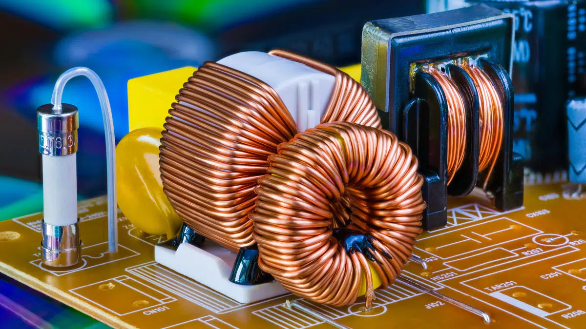
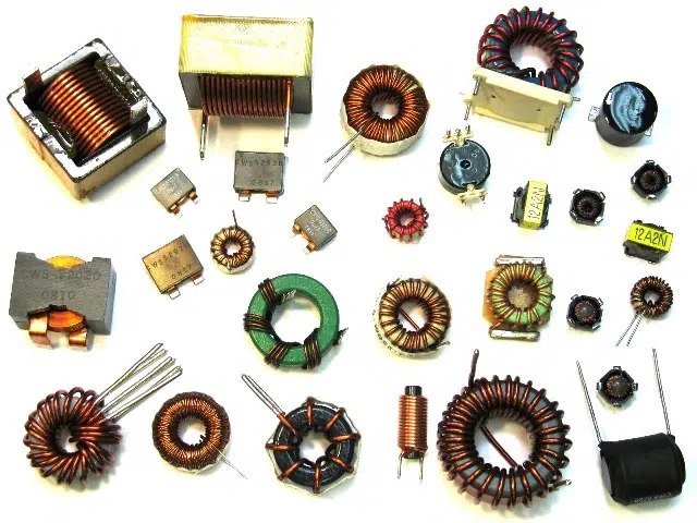
Wirewound inductors are available for various inductance values, frequencies, power handling capabilities, and applications (Figure 1).

Inductors and chokes are differentiated by how they are used. Inductors are used primarily on power and signal lines to filter differential noise and to store electrical energy in power conversion circuits. The component is referred to as a choke when used to filter common mode noise.

In the most basic implementation, an inductor consists of a coil of insulated wire (magnet wire). Inductors can be free-standing or wound on a plastic core to make an air-core inductor.

Figure 1: Wire-wound inductors are available in a wide range of shapes and sizes as needed for specific applications. 

To support higher inductances, a ferromagnetic core can be used. When a ferrimagnetic material is used for the core, it’s called an iron core inductor.

The core is a key component in an inductor and has a major impact on performance. Ferromagnetic cores have a high permeability that increases the strength of the magnetic field, resulting in higher inductance values. Laminated steel cores prevent eddy currents and improve the efficiency of inductors used at line frequencies. Soft ferrite cores are used for inductors that operate at frequencies above a few tens of kHz. Inductors designed to filter very high frequencies can be made simply by stringing a ferrite bead on a wire.

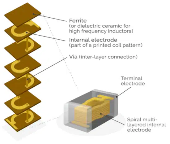
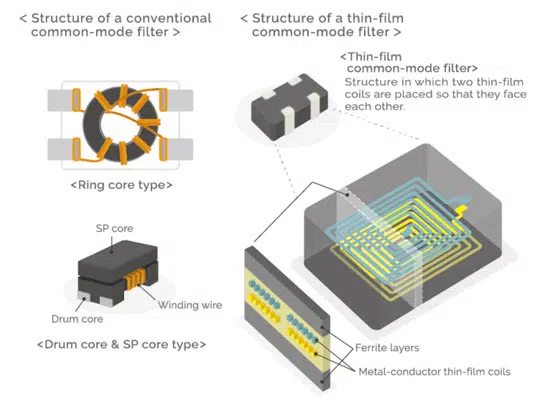
Inductors in electronic systems can be made with wire coils, multilayer structures (Figure 2a.), or thin-film materials (Figure 2b). The core of wound inductors contributes to a lower DC resistance of the windings and improves the efficiency of the inductor. Multilayer inductors consist of laminated or printed structures and are often used on signal lines as part of a filter or impedance matching circuit.

The ‘wires’ in these inductors consist of a coil pattern screen printed on multiple layers of ferrite substrate material. Their three-dimensional structure is completely covered by the ferrite, which acts as a magnetic shield and reduces leakage, making them especially suitable for high-density applications. When the frequency exceeds a few hundred MHz, ferrites experience increased losses and are not suitable as substrate material. In those applications, a dielectric ceramic substrate is substituted for the ferrite.

Figure 2a. Multilayer inductor structure; source: TDK
Figure 2b. conventional and thin-film common-mode inductor structure; source: TDK

Flat Wire Inductors

Wirewound inductors are good solutions in many applications. However, in higher frequency designs, the wires experience the skin effect where the current flows in a constrained region near the surface of the conductor, with little or no current in the central area. The skin effect results in higher AC resistance at higher frequencies. At higher frequencies, the skin depth where the current flow takes place shrinks and causes the AC resistance to increase. Opposing eddy currents induced by the alternating magnetic field are the source of the skin effect.

The use of flat wire is one possible solution to the problem of the skin effect. A flat wire has about 60% more surface area with the same cross-sectional area. With more surface area, the impact of the skin effect is reduced. Flat wires can be used to reduce the impact of the skin effect at up to about 5 MHz and also support higher inductance values and higher currents.

In addition to mitigating the skin effect, flat wire can have a winding factor of up to 95%, making for smaller inductors. In a conventional wire-wound inductor, the unused space in the gap between the windings can be up to 30%, compared with only 5% for flat wire (Figure 3).

Figure 3. Inductor flat wire benefits; Source: Bourns

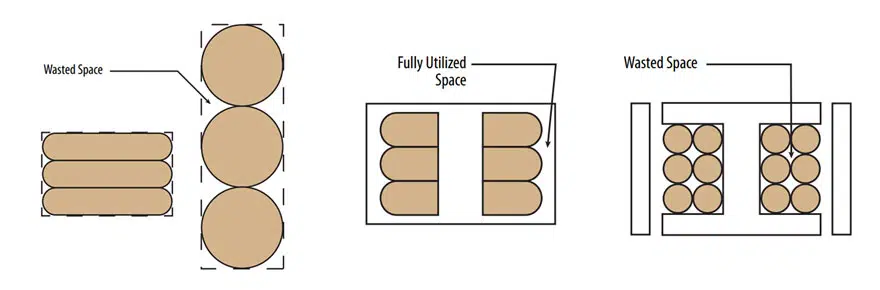
To further increase the effective density, some flat wire inductors have a powdered iron core molded directly around the wires. That eliminates all wasted space and results in higher efficiency and smaller packages for given inductance and current ratings.

Litz wire

Flat wire is great at providing a more effective surface area in conductors, reducing the impact of the skin effect, and improving packing density and thermal dissipation. But Litz wire can take those performance benefits to the next level. Litz wire also reduces losses from the proximity effect.

Figure 4: Litz wire consist of many small insulated copper wires and can be produced in both round and flat or rectangular structures.

When alternating current flows through adjacent conductors, the current distribution in each conductor will be constrained in small regions by the magnetic fields. This current crowding is called the proximity effect and increases the effective resistance of the conductors compared with the DC resistance. At high frequencies, the proximity effect can increase the AC resistance by order of magnitude compared to the DC resistance. As a result, Litz wire is often found in high-frequency and high-current inductors (and transformers) that operate at hundreds of kHz.

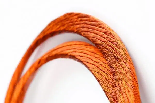
Litz wire comprises many small insulated copper wires braided or woven together. Using specific braiding or weaving patterns, the proportion of each strand at the exterior of the wire is distributed equally among the strands and results in an operational efficiency up to 100% higher than conventional wirewound inductors. Simple twisted-strand wire cannot deliver the efficiency improvement of Litz wire. Litz wire can be round or rectangular; rectangular Litz wire can support high winding factors like flat conductors, but with an even greater decrease in skin and proximity effects (Figure 4).

Copper foil

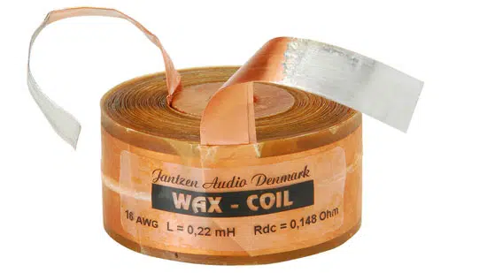
Foil inductors can be used across a range of power applications. Today, they are mostly used in audio systems such as loudspeaker crossover networks. (Figure 5). Audiophiles like the acoustic characteristics of copper foil inductors. They are fabricated with high winding tension, and the faces of the foil conductors are fused in place, making a highly stable mechanical structure. Wirewound inductors, on the other hand, may not be as stable and can allow relative motion in the audio range between the conductors resulting in frequency modulation distortion and a lower quality of sound.

Figure 5. Copper foil inductor; source: Jantzen

Foil inductors also have superior thermal dissipation enabling cooler operation even during long periods of high output power when high sound volumes are needed to fill large spaces. The copper foil is more effective at dissipating heat than wire-wound inductors, and foil inductors have a higher winding density, contributing to improved thermal dissipation. Other benefits of foil inductors include:

  • Skin effect is several orders of magnitude better than wire-wound inductors at frequencies up to 100 kHz
  • Relatively flat inductance from 5 Hz to 50 kHz, well suited for audio applications
  • Air core design eliminates saturation distortion
  • Small size and high fill factor
  • More rugged electrically and mechanically. The copper foil reduces voltage stresses between the windings and has higher mechanical strength than wire-wound inductors.
  • Lower in cost since copper foil costs less than Litz wire, and foil inductors are usually fabricated without a ferrite core.

Summary

Inductors are ubiquitous components used in a range of applications in electronic systems. While wire wound inductors using magnet wire are a common implementation, they are also fabricated using thin film materials, flat wires, Litz wires, and copper foils. Each fabrication method produces inductors with unique characteristics optimized for specific application and cost needs.

Related

Source: EEworldonline

Recent Posts

Exxelia Presents Smart Integrated Magnetics Solution at Space Tech Expo 2025 

5.11.2025
7

Murata Expands High Cutoff Frequency Chip Common Mode Chokes

5.11.2025
4

Transformer Design Optimization for Power Electronics Applications

4.11.2025
6

Microhardness — the Hidden Key to Understanding MnOx Cathode Quality in Tantalum Capacitors

3.11.2025
14

Lightweight Model for MLCC Appearance Defect Detection

3.11.2025
12

Bourns Releases High Current Metal Alloy-based, Multilayer Power Chip Inductors

31.10.2025
25

Common Mode Chokes Selection for RF Circuits in Next-Generation Communication Systems

30.10.2025
14

Capacitor Self-balancing in a Flying-Capacitor Buck Converter

30.10.2025
32

Vishay Releases Space-Grade 150 W 28V Planar Transformers

29.10.2025
27

How to Select Ferrite Bead for Filtering in Buck Boost Converter

23.10.2025
50

Upcoming Events

Nov 4
November 4 @ 12:00 - November 6 @ 14:15 EST

Wirebond Materials, Processes, Reliability and Testing

Nov 6
14:30 - 16:00 CET

Self-healing polymer materials for the next generation of high-temperature power capacitors

Nov 11
17:00 - 18:00 CET

Industrial Applications Demand More from Interconnects in Next-Gen Designs

View Calendar

Popular Posts

  • Buck Converter Design and Calculation

    0 shares
    Share 0 Tweet 0
  • Boost Converter Design and Calculation

    0 shares
    Share 0 Tweet 0
  • LLC Resonant Converter Design and Calculation

    0 shares
    Share 0 Tweet 0
  • Flyback Converter Design and Calculation

    0 shares
    Share 0 Tweet 0
  • Ripple Current and its Effects on the Performance of Capacitors

    3 shares
    Share 3 Tweet 0
  • MLCC and Ceramic Capacitors

    0 shares
    Share 0 Tweet 0
  • Dual Active Bridge (DAB) Topology

    0 shares
    Share 0 Tweet 0
  • What is a Dielectric Constant and DF of Plastic Materials?

    4 shares
    Share 4 Tweet 0
  • SEPIC Converter Design and Calculation

    0 shares
    Share 0 Tweet 0
  • Flying Capacitors

    0 shares
    Share 0 Tweet 0

Newsletter Subscription


Passive Components Blog

© EPCI - Leading Passive Components Educational and Information Site

  • Home
  • Privacy Policy
  • EPCI Membership & Advertisement
  • About

No Result
View All Result
  • Home
  • Knowledge Blog
  • PCNS

© EPCI - Leading Passive Components Educational and Information Site

This website uses cookies. By continuing to use this website you are giving consent to cookies being used. Visit our Privacy and Cookie Policy.
Go to mobile version