This article, authored by Vladimir Azbel, Ph.D., a semiconductor process reliability engineer consultant, provides deep inside explanation of energy dissipation during formation of tantalum capacitor dielectric that may have an impact to the dielectric quality and tantalum capacitor reliability.
Tantalum capacitor anode formation is conventionally controlled using macroscopic power (P = U·I), but this approach masks a critical problem: energy dissipation during formation is not uniform—it concentrates within interparticle necks where current density and thermal stress reach extreme levels. This structural analysis reveals why formation processes that appear thermally safe at the system level can still produce localized overheating, dielectric defects, and reliability failures.
Key Takeaways
- Energy dissipation during tantalum capacitor formation is highly localized, which can lead to dielectric defects and reliability failures.
- Current evaluation methods using total power do not account for localized electro-thermal conditions within interparticle necks.
- A structural framework based on local electro-thermal balance is necessary to improve formation control and prevent overheating.
- The parameter ψ helps quantify the impact of structure on current density and energy dissipation, linking it to tantalum capacitor reliability.
- Adaptive control strategies must focus on local energy density rather than global power inputs for optimal performance.
The formation of tantalum capacitor anodes is conventionally evaluated using macroscopic power, implicitly assuming that thermal conditions are governed at the level of the entire anode.
In this work, it is shown that this assumption is fundamentally incomplete.
A structural analysis demonstrates that energy dissipation during formation is highly localized within interparticle necks — regions of minimal conductive cross-section where current density is inherently concentrated. As oxide growth progressively constricts the conductive pathway, the combined effect of Joule heating and exothermic reactions leads to extreme energy localization.
Model-based evaluation of a 10 µF anode formed at 200 V shows that while the average power density remains on the order of ~10² W/cm³, the local energy density within the neck reaches ~10⁵ W/cm³, exceeding it by several orders of magnitude.
This disparity explains why formation conditions that appear thermally safe at the macroscopic level can still result in localized overheating and dielectric defects.
The results establish a transition from global power-based evaluation to a structural framework based on local electro-thermal balance, providing a physical basis for adaptive formation control and defining the limits of miniaturization in tantalum capacitor anodes.
Introduction
The formation of tantalum capacitor anodes is conventionally evaluated using the macroscopic relation P = U·I. This parameter defines the total energy input to the anode and is widely used as a practical measure of the thermal regime during formation.
However, this approach creates a fundamentally misleading engineering intuition.
While P = U·I describes how much energy is supplied to the system, it does not describe where this energy is dissipated. As a result, formation processes may appear thermally safe at the macroscopic level, while still producing localized overheating and dielectric defects.
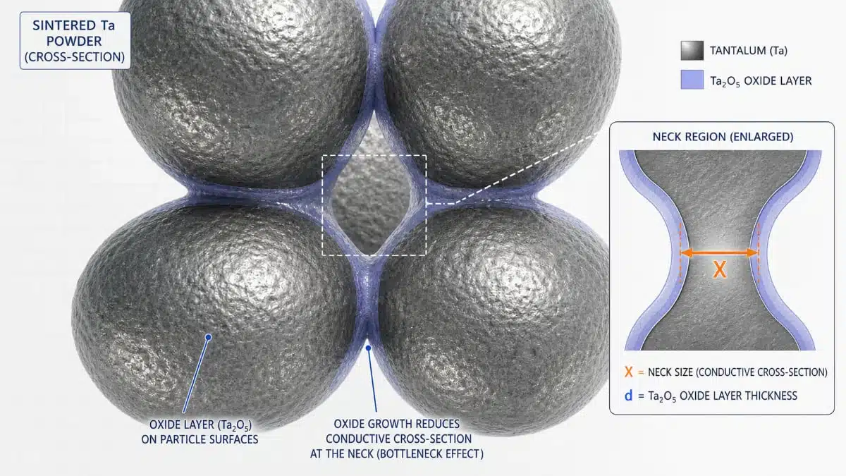
This contradiction originates from the porous nature of the anode. Electrical conduction does not occur uniformly across the volume, but is concentrated within interparticle necks — regions characterized by minimal conductive cross-section. These regions act as bottlenecks for current transport and therefore define the local electro-thermal regime.
In this work, it is shown that the formation process is not governed by total power, but by local energy density within the interparticle necks. A structural and quantitative analysis demonstrates that local thermal conditions differ by several orders of magnitude from macroscopic estimates.
This establishes the need for a transition from global power-based evaluation to a structural framework based on local electro-thermal balance.
Structural Origin of Energy Localization
The porous anode structure consists of primary particles connected by interparticle necks formed during sintering. These necks define the conductive pathways within the anode.
The geometry of interparticle necks is determined during sintering and can be described analytically assuming spherical primary particles.
In this representation, the neck size is related to the degree of particle approach driven by diffusion processes during sintering, forming a contact region whose characteristic dimension defines the conductive pathway.
Thus, sintering establishes the geometric framework (X), while formation defines its functional role through oxide growth and electro-thermal interaction.
During formation, oxide growth progressively consumes the metallic cross-section of these pathways. As a result:
- the effective conductive area decreases
- electrical resistance increases
- current density rises locally
Under these conditions, energy dissipation becomes highly localized due to the combined effect of:
- Joule heating (I²R)
- exothermic oxide formation
Thus, the interparticle neck is not merely a structural feature.
It becomes the region where the electro-thermal regime is physically established.
Geometrical Model of the Interparticle Neck Before and After Formation
The geometry of the porous tantalum anode is defined during sintering and subsequently modified during anodic formation. (see Fig.1)
Before formation, the structure consists of sintered particles of diameter
D=2Rp
connected by interparticle necks of characteristic size X, which define the conductive pathways within the anode.
During anodic formation, an oxide layer (Ta₂O₅) grows on the internal surface of the structure. This process reduces the metallic core of each particle from radius Rp to r1p, such that the oxide thickness is given by:
d=Rp−r1p
As oxide growth occurs from all internal surfaces, the conductive pathway within the interparticle neck is reduced from its initial size X to an effective value approximated by:
Xeff≈X−2d
This geometrical transformation directly links the formation process to the electrical behavior of the anode, as the reduction in conductive cross-section leads to increased current density and localized energy dissipation.
To quantify this effect, a dimensionless structural parameter is introduced:
ψ=d/X
The parameter ψ represents the fraction of the conductive pathway occupied by the dielectric phase and serves as a first-order indicator of structural constriction within the neck.
As ψ increases, the conductive pathway becomes progressively limited, transitioning the neck from a geometrical connection into a thermally critical region governing local overheating and dielectric reliability.
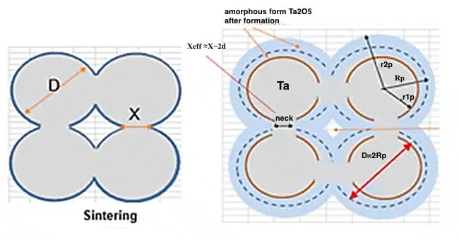
(b) After anodic formation, an oxide layer of thickness d develops along the internal surface, reducing the metallic core to radius r₁ₚ and the effective conductive pathway to approximately (X − 2d).
The parameter ψ represents the degree of structural constriction and quantifies the fraction of the conductive pathway occupied by the dielectric. Increasing ψ leads to increased current density and localized energy dissipation within the neck.
As illustrated in Figure 1, oxide growth progressively reduces the effective conductive pathway within the interparticle neck. The parameter ψ provides a direct measure of this structural constriction and links geometry to local electro-thermal conditions.
Model and Quantitative Evaluation
To quantitatively evaluate the scale of energy localization, a model-based calculation was performed for a 10 µF anode formed at 200 V.
| Level | Oxide Volume (cm³) | Power (W) | Power Density (W/cm³) |
|---|---|---|---|
| Whole anode | 0.0048 | 0.6 | ~1.25×10² |
| Local neck | 5.98×10⁻¹³ | 3×10⁻⁷ | ~5×10⁵ |
Although the absolute power associated with a single neck is extremely small, its confinement within a very small volume leads to extremely high local energy density.
Key Result: Scale-Dependent Thermal Regime
The same physical relation, P/V, leads to fundamentally different thermal regimes depending on the spatial scale.
At the macroscopic level, the process appears thermally moderate.
At the microscopic level, within the neck, the energy density is several orders of magnitude higher.
This explains a critical engineering observation: Global thermal stability does not guarantee local electro-thermal stability.
Implications for Formation and Defect Generation
The extreme localization of energy provides a physical explanation for the origin of dielectric defects.
Even when formation conditions appear safe in terms of total power, local overheating within the neck can:
- accelerate defect formation
- destabilize oxide growth
- increase leakage current (DCL)
Thus, the failure mechanism is not governed by average conditions, but by localized electro-thermal extremes within the interparticle necks.
Link to Miniaturization
The problem becomes more pronounced with increasing specific capacitance (CV/g).
Higher surface area powders result in:
- smaller primary particles
- reduced neck size (X)
- increased current density
To quantify the structural effect, the parameter ψ (introduced in Section 3)is used.
The parameter ψ represents the fraction of the conductive pathway occupied by the dielectric phase and serves as a first-order structural indicator of resistive constriction.
As ψ increases, the effective metallic cross-section is progressively reduced, leading to a nonlinear increase in local current density and energy dissipation.
From a physical standpoint, ψ defines the transition from stable conduction to a regime dominated by localized electro-thermal effects. Simultaneously, higher formation voltages increase oxide thickness (d), further constricting the conductive pathway.
This leads to a progressive increase in the structural parameter:
ψ = d/X
As ψ increases, the system becomes increasingly sensitive to local overheating.
Engineering Consequence: Need for Adaptive Control
If the formation process is governed by local energy density, then control strategies based on global parameters are inherently insufficient.
Formation current should not be treated as a fixed parameter.
Instead, it must adapt to the evolving structure of the anode.
Such control can be implemented using a quantitative electro-thermal model that evaluates the balance between heat generation and heat removal (Δ = Q_{rem} / Q_{gen}), enabling the identification of safe formation conditions under evolving structural constraints.
The implementation of this model, including a unified calculation framework linking structural, electrical, and thermal parameters, is available in an open-access form (Zenodo DOI: 10.5281/zenodo.19482660).
This requires control based on local electro-thermal balance, rather than total power input.
Conclusion
The conventional use of P = U·I provides a measure of total energy input but does not capture the spatial distribution of energy within the anode. It is shown that the formation process is governed by localized electro-thermal conditions within interparticle necks, where energy density can exceed macroscopic estimates by several orders of magnitude.
The interparticle neck must therefore be considered as a localized electro-thermal reactor that defines the conditions of dielectric formation and reliability.
The transition from global power-based evaluation to local energy-based analysis is essential for understanding defect formation, defining the fundamental limits of miniaturization, and enabling adaptive control of the formation process.