


This article based on post High-Voltage Resistor Selection Checklist prepared by Exxelia provides comprehensive selection guide for high voltage resistor in a form of selection checklist for engineers and professionals in the electrical and electronics industries.
Introduction
The resistor is the most common and well-known passive electrical component.
A resistor is a device connected into an electrical circuit to introduce a specified resistance. The resistance is measured in Ohms. There are various resistor types and resistor symbols.
As stated by Ohms Law (E=IR), the current through the resistor will be directly proportional to the voltage across it and inversely proportional to the resistance. Resistors have numerous characteristics that determine their accuracy during use.
The performance indices affect the accuracy to a greater or lesser extent depending on the application. Some of these indices are: Tolerance at DC, Temperature Coefficient of Resistance (TCR), Voltage Coefficient of Resistance (VCR), Noise, Stability with respect to Time and Load, Power Rating, Physical Size, and Mounting Characteristics. Resistor networks typically require temperature and voltage tracking performance.
Selection Requirements
- Determine the resistance in ohms and watts.
- Determine the proper physical case size as controlled by voltage, watts, mounting conditions, and circuit design requirements.
- Select the resistor that meets your needs for type, termination and mounting.
STEP 1 : DETERMINE THE RESISTANCE IN OHMS AND WATTS.
OHM’S LAW:
Ohm’s Law
Ohm’s Law describes the relationship between voltage (V), current (I), and resistance (R) in an electrical circuit:
- V = I × R (Voltage = Current × Resistance)
- I = V / R (Current = Voltage ÷ Resistance)
- R = V / I (Resistance = Voltage ÷ Current)
Ohm’s Law, as shown in the above formula, enables one to define the voltage (V), current (I), or resistance (R) when two of the three terms are known. When current and voltage are unknown they must be measured in the model circuit.
POWER LAW:
Power Law
The Power Law defines the rate at which electrical energy is converted into heat, light, or motion in a circuit. It relates power (W) to voltage (V), current (I), and resistance (R):
- W = I² × R (Power = Current squared × Resistance)
- W = V × I (Power = Voltage × Current)
- W = V² / R (Power = Voltage squared ÷ Resistance)
Watts (power) can be determined from the above formulas that are derived from Ohm’s Law. R is measured in Ohms, V in volts, I in amperes, and W in watts.
Watts must be accurately determined before resistor selection. Simply stated any change in voltage or current produces a much larger change in wattage (heat dissipated by the resistor). The effects of relatively small increases in voltage or current must be determined because the increase in wattage may be significant enough to influence resistor selection. As stated in the above formulas the wattage varies as the square of the current or voltage. Allowances should be made for maximum possible voltage.
STEP 2 : DETERMINE THE PROPER PHYSICAL CASE SIZE AS CONTROLLED BY VOLTAGE, WATTS, MOUNTING CONDITIONS, AND CIRCUIT DESIGN REQUIREMENTS.
POWER RATING AND PHYSICAL SIZE:
A resistor operated at a constant wattage will reach a steady temperature that is determined largely upon the ratio between the substrate size (surface area) and the wattage dissipated. Temperature stabilizes when the sum of the heat loss rates (by radiation, convection, and conduction) equals heat input rate (wattage). The larger the resistor surface area per watt to be dissipated, the greater the heat loss rate and therefore the lower the temperature rise.
Free Air Wattage Rating (Maximum Power Rating) is defined as the wattage rating of resistors as established under specified standard conditions. The absolute temperature rise for a specific resistor is roughly related to the area of its radiating surface. It is also dependent upon a number of other factors such as thermal conductivity, ratio of length to width, heat-sink effects of mounting, and other minor factors.
The precise temperature limits corresponding to 100% rated wattage are somewhat arbitrary and serve primarily as design targets. Once a wattage rating has been assigned on the basis of an empirical hot spot limit, the verification of its correctness must be established through long term load life test based on performance and stability standards rather than the measurement of hot spot temperature.
STEP 3 : SELECT THE RESISTOR THAT MEETS YOUR NEEDS FOR TYPE, TERMINATION AND MOUNTING.
RESISTOR SELECTION:
Select the most suitable resistor that meets the requirements of the application. Refer to the appropriate data sheet to determine part number.
WATTAGE RATING:
To allow for the differences between actual operating conditions and the Free Air Wattage Rating it is a general engineering practice to operate resistors at less than the nominal rating.
VOLTAGE RATING:
Determine maximum applied (working) voltage that the resistor will be exposed to and select the appropriate package size.
PULSE OPERATION:
When a resistor is operated in a pulse application, the total power dissipated by the resistor is a function of the pulse’s duty cycle. Typically, one will define the number of joules of energy the resistor must dissipate and choose a resistor accordingly.
HIGH FREQUENCY:
Check suitability of the resistor types to operate at high frequencies. High frequency resistor design and construction shall exhibit very low capacitance and a non-inductive design.
MILITARY AND OTHER SPECIFICATION:
The special physical operating and test requirements of the applicable industrial or military specification must be considered.
EFFECT OF THE POWER RATINGS ON COMPONENTS
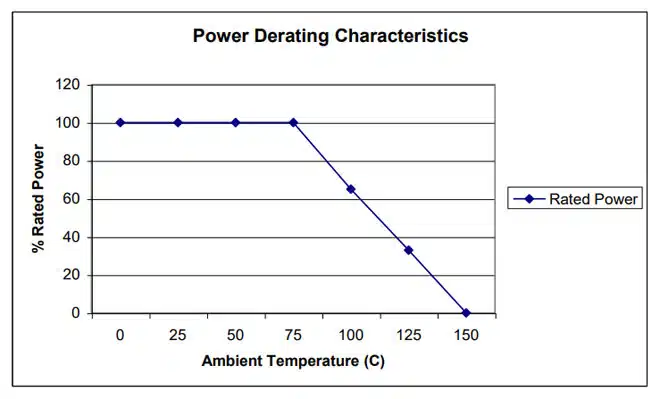
All the components of an electrical apparatus including resistors, capacitors, rectifiers, and semiconductors have their own limitations as to the maximum temperature at which they can reliably operate. The attained temperature in operation is the sum of the ambient temperature plus the temperature rise due to the heat dissipation in the equipment.
Ambient Temperature Derating, below defines the percent of full load that power resistors can dissipate as a function of ambient temperature.
TEMPERATURE COEFFICIENT OF RESISTANCE
Temperature Coefficient of Resistance (TCR) is expressed as the change in resistance in ppm (0.0001%) with each degree of change in temperature Celsius. MIL STD 202 Method 304 is often referenced as a standard for measuring TCR. This change is not linear with temperature. TCR is typically referenced at +25°C and changes as the temperature increases or decreases. It can be either a bell or S shaped curve.
It is treated as being linear unless very accurate measurements are required, then a temperature correction chart is used. A resistor with a TCR of 100 ppm will change 0.1% over a 10-degree change and 1% over a 100-degree change. An example of a TCR curve can be found in the application note:
The following formula expresses the rate of change in resistance value per 1°C in a prescribed temperature range.
Temperature Coefficient of Resistance (TCR)
The TCR quantifies how the resistance of a material changes with temperature. It is typically expressed in parts per million per degree Celsius (ppm/°C):
TCR (ppm/°C) = (R − R₀) / R₀ × 1 / (T − T₀) × 10⁶
Where:
- R = Resistance at temperature T
- R₀ = Resistance at reference temperature T₀
- T = Measured temperature (°C)
- T₀ = Reference temperature (°C)
In the context of a resistor network, this TCR value is called absolute TCR in that it defines the TCR of a specific resistor element. The term TCR tracking refers to the difference in TCR between each specific resistor in the network.
VOLTAGE COEFFICIENT OF RESISTANCE
The Voltage Coefficient of Resistance is the change in resistance with applied voltage. This is entirely different and in addition to the effects of self-heating when power is applied. A resistor with a VCR of 100 ppm/V will change 0.1% over a 10 Volt change and 1% over a 100 Volt change. VCR becomes very important in high Ohmic value resistor (100M Ω and above) where typical VCRs can be greater than 1000 ppm/V to specify the voltage that will be applied. Failing to do this may result in a resistor that will not meet your specification.
The rate of change in resistance value per 1 volt in the prescribed voltage range is expressed by the following formula:
The VCR describes how a resistor’s value changes with applied voltage. It is typically expressed in parts per million per volt (ppm/V):
VCR (ppm/V) = (R₀ − R) / R₀ × 1 / (V₀ − V) × 10⁶
Where:
- R = Resistance at voltage V
- R₀ = Resistance at reference voltage V₀
- V = Measured voltage (V)
- V₀ = Reference voltage (V)
In the context of a resistor network, this VCR value is called the absolute VCR in that it defines the VCR of a specific resistor element. The term VCR tracking refers to the difference in VCR between each specific resistor network.
SUMMARY
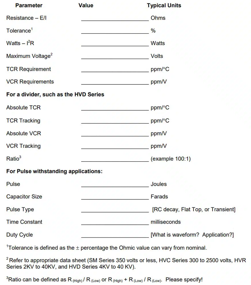
When specifying a resistor, the following parameters MAY be of interest. Please use this chart to help you define the operating characteristics for your specific application. All of them may not important for your specific application.
Below is an example of a resistor selection form template.
Further read: Designing with High Voltage Resistors: 10 Top Tips for Success


